


Product engineering · Switzerland
Product Design.
DOMTEKNIKA develops products and mechanisms for industrial companies and innovators, from the initial architecture to components prepared for industrialisation.
Discuss your requirementsTechnical insight
Designing for the whole life of a part.
From the first prototypes, we examine how a part will be manufactured, assembled, used and dismantled. These constraints inform geometry, materials and interfaces before the product definition is frozen.
| Life stage | What we consider | Design implications |
|---|---|---|
| Production and assembly | Intended processes, volumes, functional tolerances and assembly sequence. | Adapt geometry, fasteners and drawings to the manufacturing methods. |
| Use and maintenance | Loads, wear, environment and access to replaceable parts. | Size components and plan maintenance operations. |
| End of life | Disassembly, material separation and intended recycling routes. | Assess joining methods and material combinations during design. |
A challenge, a real project
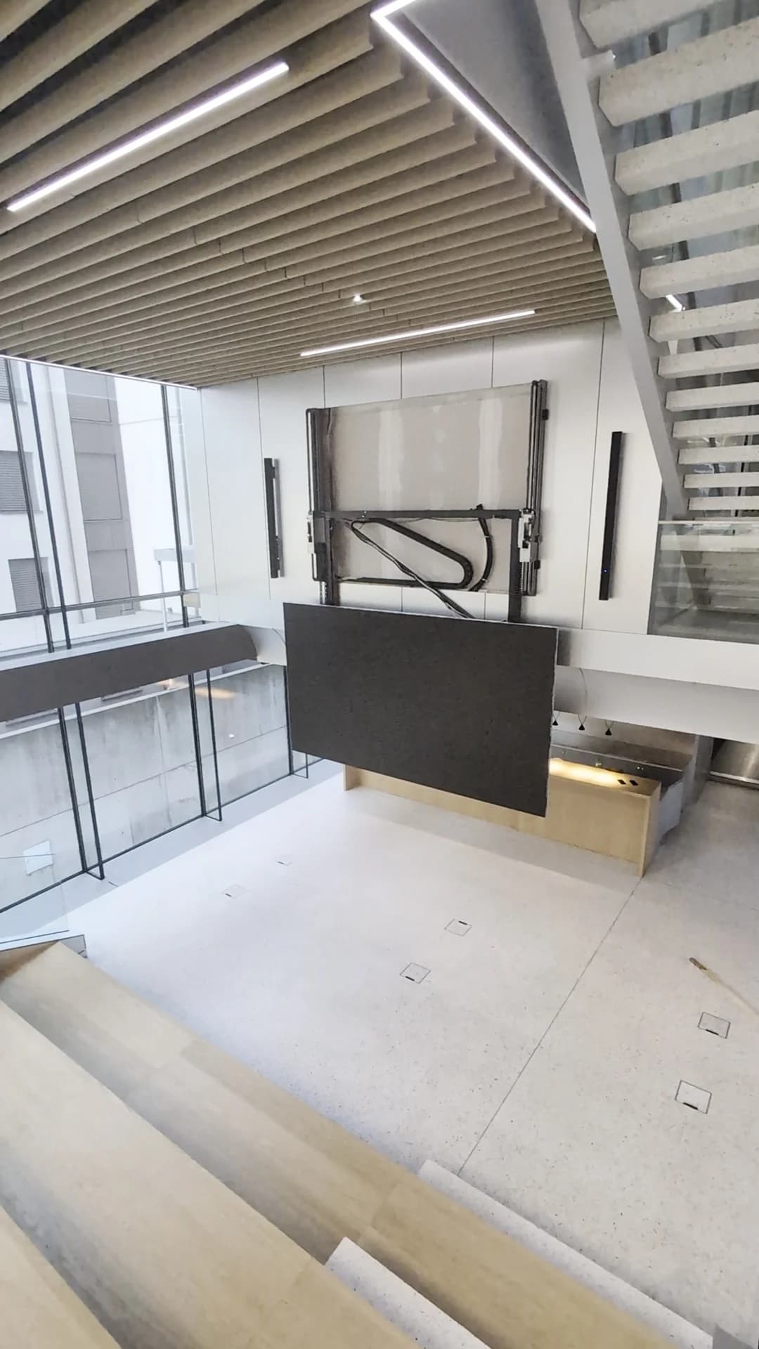
Velum Sky amphitheatre screen
Lowering a screen while preserving the architectural view.
At the Velum Sky amphitheatre in Geneva, the guides had to remain hidden with the screen raised. During descent, the screen is fully cantilevered. DOMTEKNIKA designed the guidance, stiffness and lifting mechanism around these constraints, integrating a precise function into its surroundings.
View projectWhen to involve us
Translate a required function into a feasible mechanical architecture.
- Design a custom part or mechanism
- Improve a product that is difficult to manufacture
- Prepare drawings for a prototype or production
Our approach
From the first prototypes, we relate material and assembly choices to manufacturing, use and the end of a part’s life. CAD helps develop an architecture that addresses these constraints and the product’s interfaces.
Define interfaces
Identify loads, available space and interacting parts.
Develop the solution
Build the CAD design, material choices and assemblies.
Prepare validation
Define the checks and technical documentation.
What you receive
- Mechanical architecture and CAD models
- Component, interface and assembly definition
- Documentation for the stage, including toleranced 2D drawings and a bill of materials where agreed
CAD models clarify interfaces and prepare validation. Depending on the project, development continues through prototypes, calculations or refinement for production.
We agree the scope, tests and deliverables with you before work begins.
Frequently asked questions.
Explore the full FAQ7 questions
Do we need to have a design already?
No. We start where you are: a blank-sheet idea, sketches, CAD models, a prototype or an existing product. We then clarify the functions to develop, interfaces to preserve and constraints to address.
Does design include manufacturing?
The documentation can support prototyping or production. Manufacturing, testing and industrial support are specified within the agreed scope.
What can serve as the starting point?
Drawings, CAD models, sketches, photographs and observations from an existing component can help. We identify missing information for the requested work, particularly interfaces, loads and functional dimensions.
How do you select a component’s material?
The choice depends on function, loads, environment, weight and the manufacturing process. Assembly and cost constraints are also compared to identify a material suited to the product.
Why do tolerances matter?
They define acceptable dimensional variations in manufactured parts. In an assembly, these variations affect clearance, guidance and clamping. Tight tolerances should therefore meet a functional need.
How is a component prepared for manufacturing?
The geometry and specifications are assessed against the intended process. Access, functional surfaces, tolerances and assembly steps are reviewed to prepare documentation consistent with manufacturing and inspection.
How can maintenance and repair be considered during design?
Identify the parts that need inspection, cleaning or replacement, and the access required. Fasteners, disassembly and cable routing should account for these tasks and the operating conditions.
For our first conversation
.Which mechanism would you like to develop?
Describe your idea or the product you want to improve. If you have sketches, drawings or CAD models, they will help clarify the components, interfaces and manufacturing constraints.
Discuss your requirements