


US2022338602 (A1)
防风雨及遮阳装置框架.
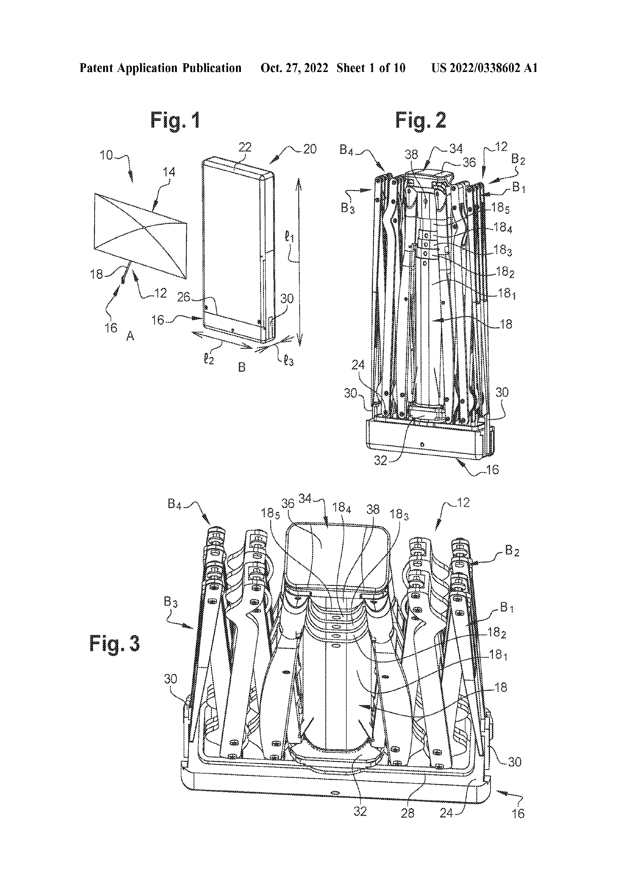
一种用于天气和/或防晒装置的可展开框架,包括: 具有纵向轴线的桅杆,其上安装有滑块,以便在框架关闭的第一位置和框架打开的第二位置之间滑动;至少一个肋通过拉伸器连接到滑行件,该肋包括连接到由立柱一端承载的凹口的端部,其中该肋包括由第一部分和第二部分形成的第一段,第一部分和第二部分可围绕第一部分的延伸轴线相对于彼此移动,肋的第一部分的第一部分通过绕轴线的枢转连接件连接到凹口,该轴线垂直于倾斜于立柱的纵向轴线倾斜的平面,使得在第一闭合位置中,在框架的第二打开位置中,肋的第一段沿着柱延伸,并且在框架的第二打开位置中,肋的第一段移动远离柱。
- 公开号
- US2022338602 (A1)
- 公开日期
- 2022-10-27
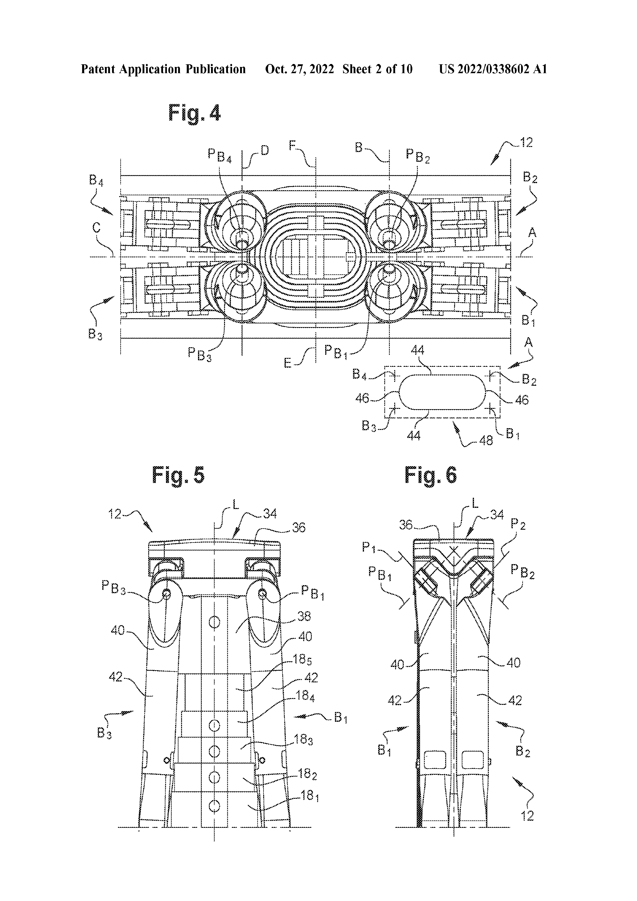
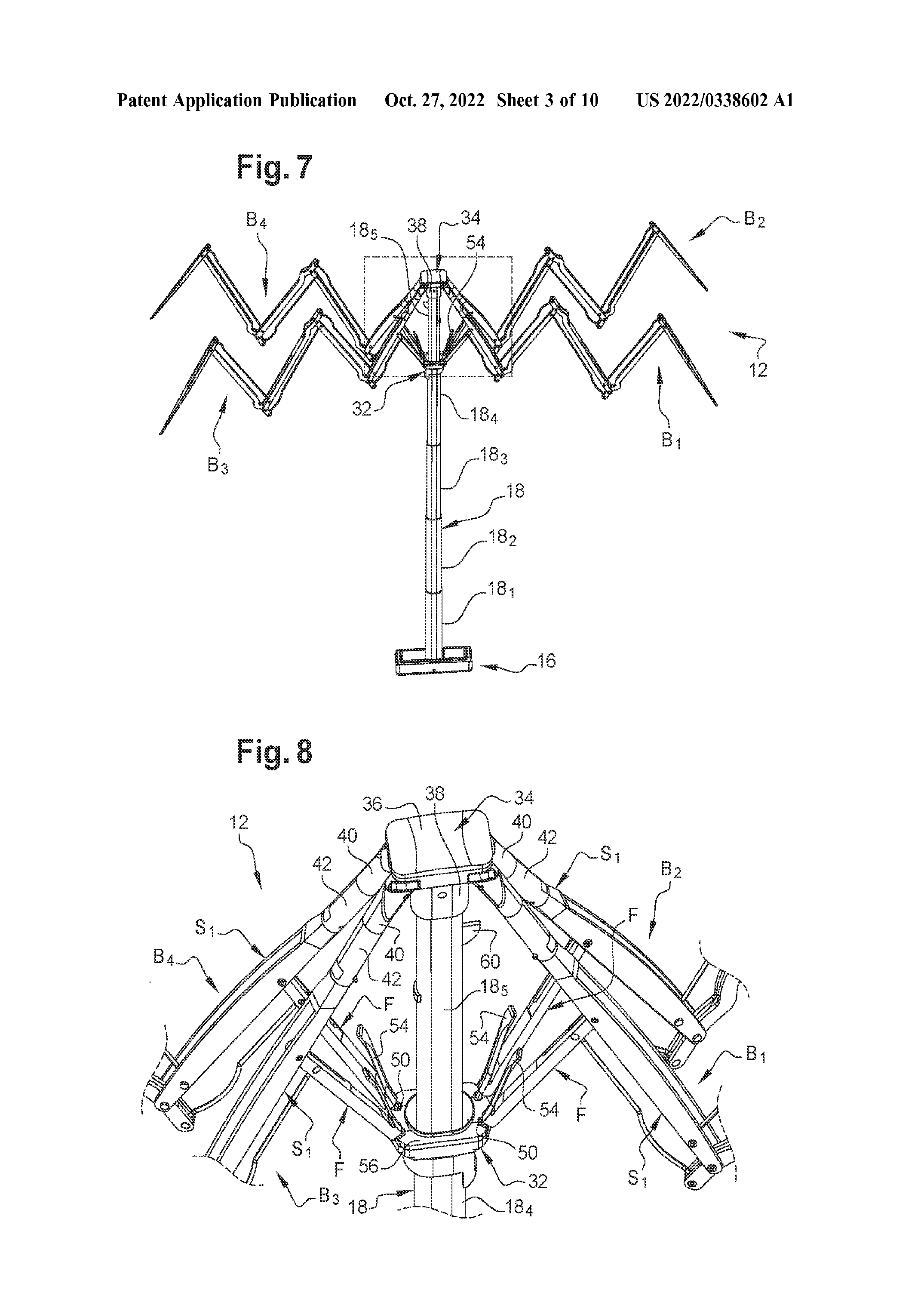
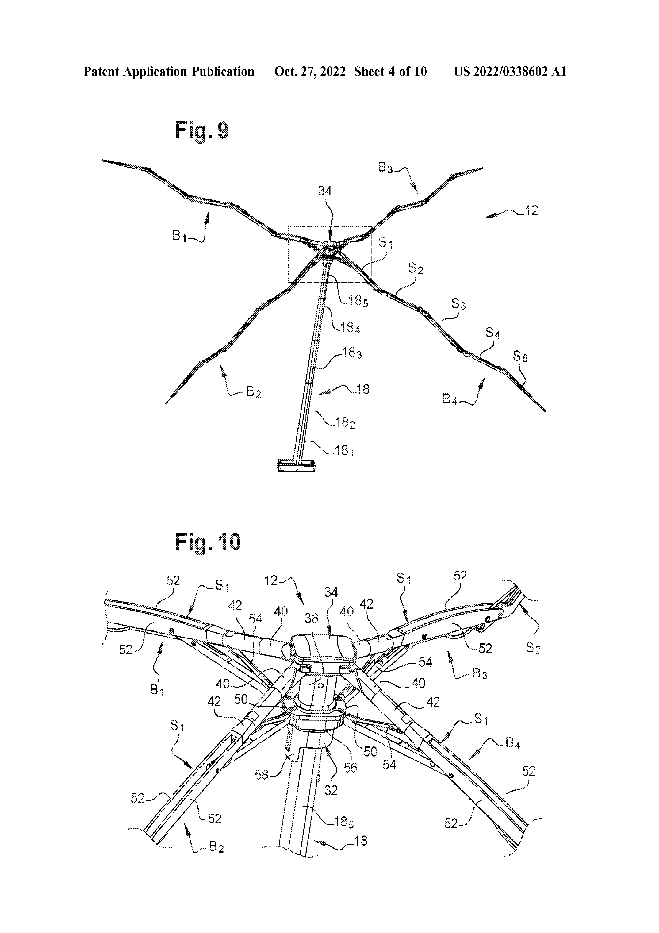
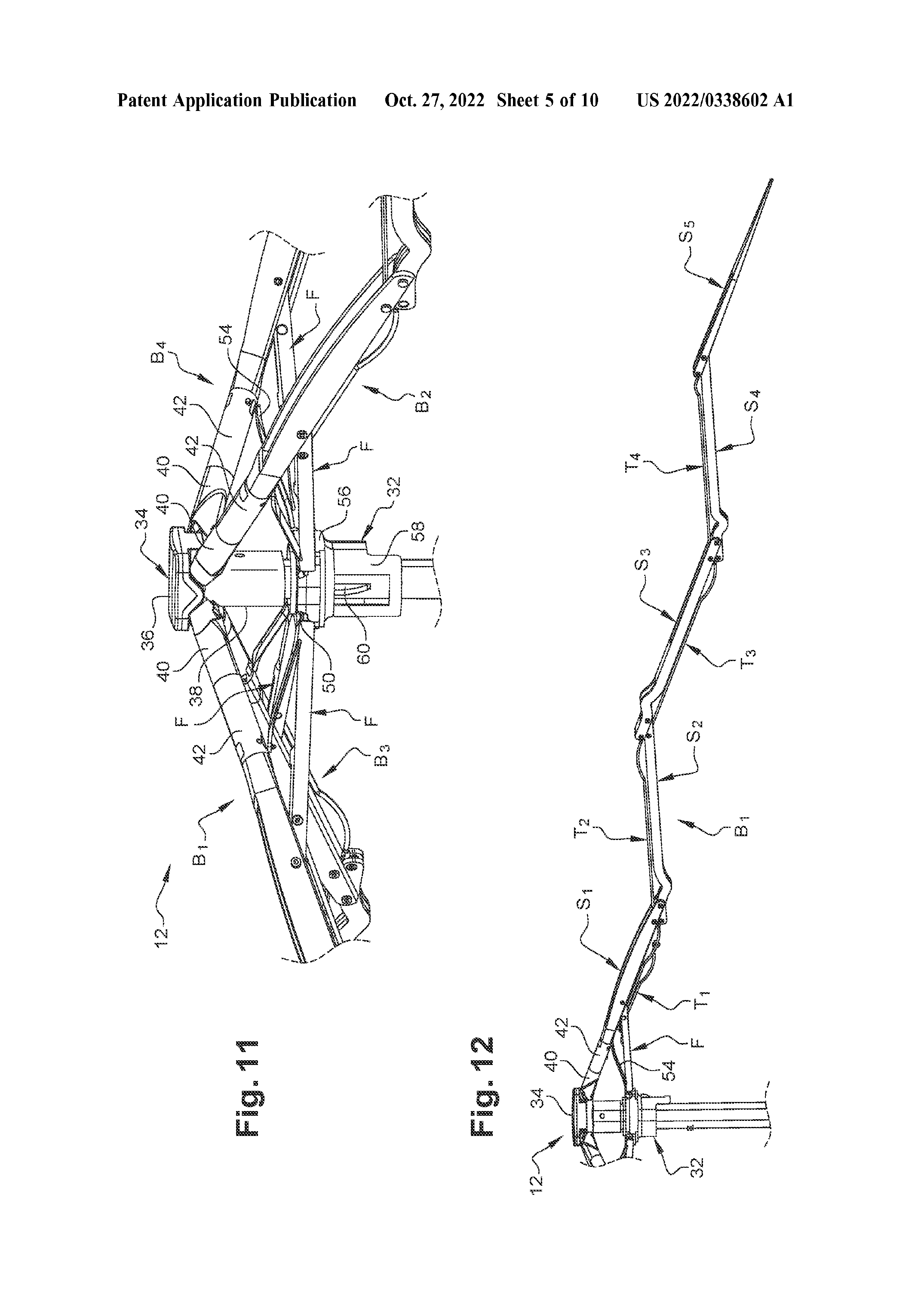
- 优先权日
- 2019-09-06
- 发明人
- THULIEZ JEAN-LUC [CH]; HEISEL GUILLAUME [CH]; QUERRY HECTOR [CH]; ZIMMERMANN ROBIN [CH]; CROZIER ETIENNE [CH]
- 申请人
- CHEVILLARD ERICK [CN]; CHEVILLARD ERIC [CN]
- 分类
- Classification: - internationale A45B19/10; A45B23/00; A45B25/02; A45B25/24 - coopérative A45B19/04 (US); A45B19/10 (EP, US); A45B2023/0006 (US); A45B2200/1081 (US); A45B25/02 (EP, US); A45B25/10 (EP); A45B25/16 (EP); A45B25/24 (EP, US);
专利族公开文本
相关项目
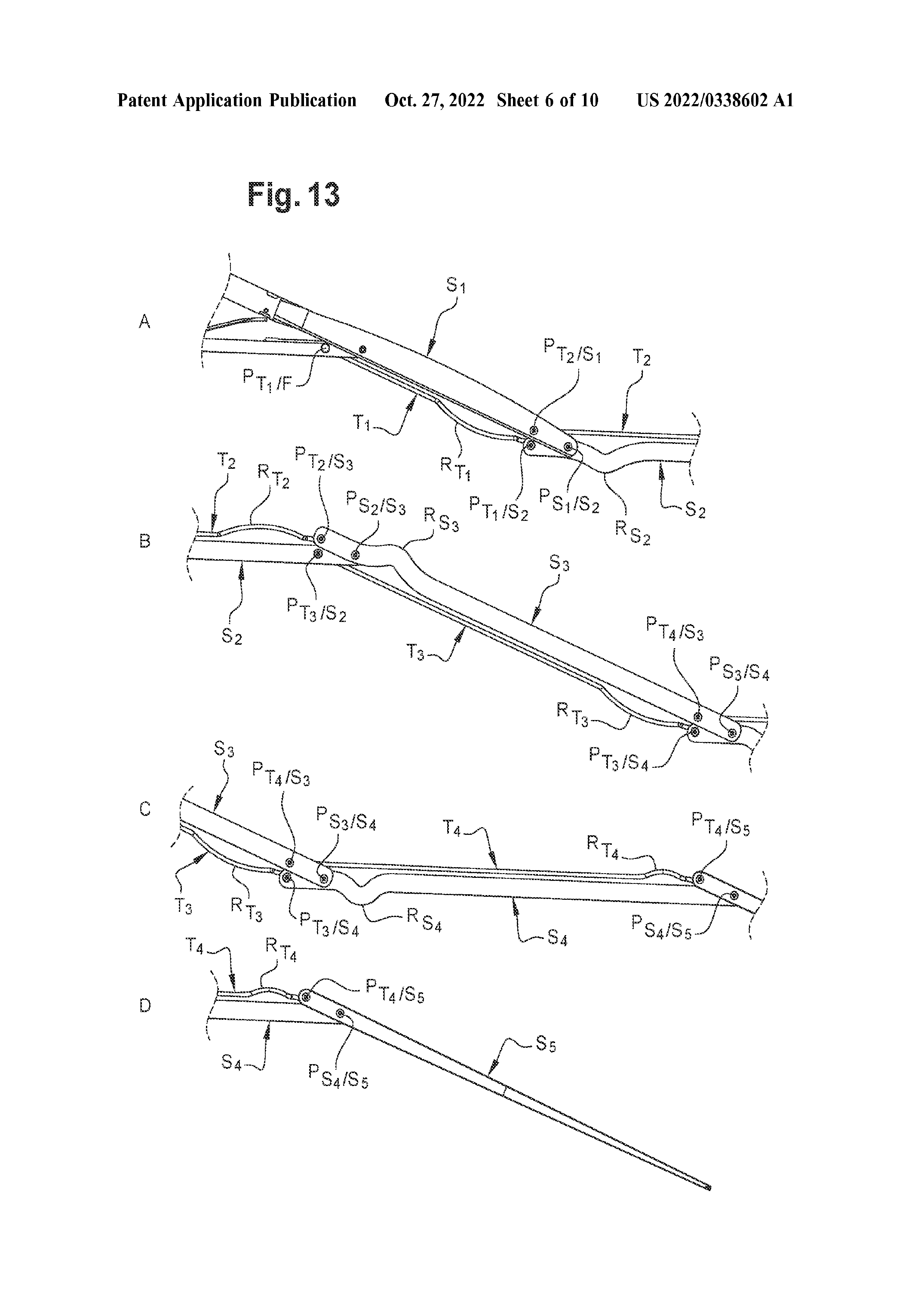
项目图片
说明
TECHNICAL FIELD OF THE INVENTION
[0001] The field is that of the devices of protection of the bad weather and/or the sun. STATE OF THE ART
[0002] Classically, a device for protection against the bad weather and/or the sunlight, such as an umbrella, a parasol or a sunshade, comprises a frame comprising a mast which may or may not be telescopic, on which a runner is mounted so that it can slide between a first position in which the device is closed and a position in which the device is open. The frame comprises ribs connected to a notch or support attached to one end of the mast and to the runner by means of stretchers or sub-ribs.
[0003] In one embodiment, it has been proposed to attach the ends of the ribs to a circumferential wire integral with the notch. The ends of the stretchers opposite to those connected to the ribs are connected to the runner by another circumferential wire integral with the runner. The deployment of the frame is achieved by sliding the runner which induces a deployment of the ribs. The angular spacing of the ribs is obtained by the tensioning of the protective fabric fixed to the ribs and by the connection by wire of the ribs and the stretchers which authorize an angulation of the ribs the ones relatively to the others. If this type of system can be very compact in closed position, it proves in practice to be very fragile to use because of the not very rigid connections, on the one hand, of the stretchers to the runner and, on the other hand, of the ribs to the notch.
[0004] Note that a weather protection device has the primary function of protecting from rain but can also be used to protect from the sun. Also a sun protection device that has the primary function of protecting from the sun can also be used to protect occasionally from the rain.
[0005] Also, a protective device as described above and used in its function of protection from the weather, necessarily turns out to be wet when it is closed again immediately after use in the rain for example. Thus, when the user arrives at a given location (restaurant, work,...) it is known to place the device in a receiving container, for example cylindrical, allowing water to flow downwards to allow drying of the device fabric. Another method consists in deploying the device in a dry place (garage, covered terrace,...) in order to carry out the drying of the fabric. It is understood that either method requires the device to be stored for a fairly long period of time and does not make it possible for the user to carry the device in a closed state due to the presence of water drops on the fabric, in a bag for example, the surrounding belongings then being wet.
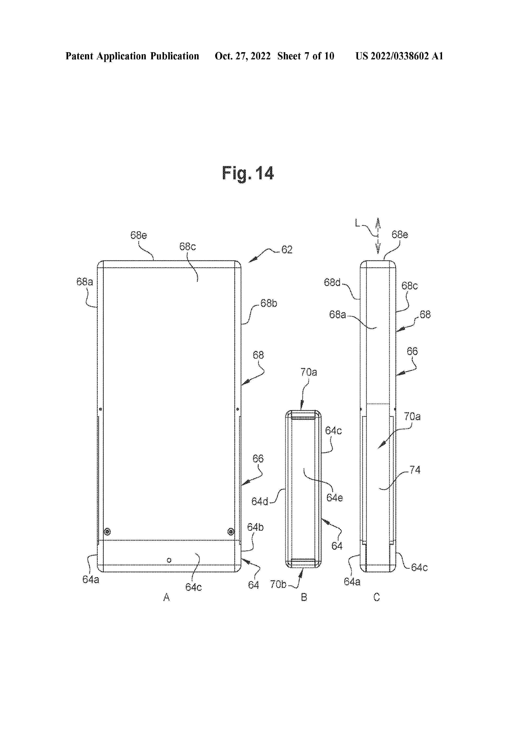
[0006] The invention aims to remedy all or part of the above-mentioned problems and drawbacks in a simple and reliable manner. PRESENTATION OF THE INVENTION
[0007] Thus, the present document relates to a deployable frame, in particular for a weather and/or sun protection device, comprising: a mast with a longitudinal axis on which is mounted a slider that slides between a first position in which the frame is closed and a second position in which the frame is open; at least one rib connected by a stretcher to the runner, the rib comprising an end connected to a notch carried by one end of the mast, characterized in that: the rib comprises a first segment formed by a first part and a second part that are movable with respect to each other about the extension axis of said first segment, the first part of the first segment of the rib is connected to the notch by a pivot connection about an axis which is perpendicular to a plane inclined obliquely to the longitudinal axis of the mast so that in the first closed position of the frame the first segment of the rib extends along the mast and in the second open position of the frame the first segment of the rib is moved away from the mast.
[0012] According to the proposed configuration, when the frame is deployed, the first segment articulated by a pivot connection to the notch can thus move away from the mast by pivoting around an oblique axis, while the second part of said segment can move away from the mast while performing a rotational movement around the extension axis of the first segment. Thus, the attachment of a protective cloth can be fixed to the second part of the first segment and the cloth does not undergo a rotational movement around the axis of the segment. Moreover, the mechanical connection of the first segment to the notch allows to guarantee an increased rigidity of the connection of the rib to the notch compared to the previous technique while ensuring a distance of the rib from the mast when the frame is in its second opening position. According to another characteristic, a first end of the stretcher can be connected to the runner by a ball-and-socket connection. It could also be connected to the mast via a circumferential wire integral with the runner.
[0013] The ball-and-socket connection may comprise a spherical part carried by the first end of the stretcher and housed in a cavity of complementary shape of the runner. The reverse would also be possible, i.e. a cavity carried by the first end of the stretcher and a spherical part carried by the runner.
[0014] A second end of the stretcher can be pivotally connected to the second part of the first segment of the rib. In combination with the ball-and-socket connection of the first end of the stretcher, this configuration provides further increased rigidity of the rib/stretcher assembly due to the absence of circumferential play, i.e. around the axis of the mast, of the first end of the rib with the runner.
[0015] Also, elastic means can be configured to exert a force tending to deploy the frame when it is in its first position. In particular, they may comprise an elastic member interposed between the first segment and the mast when the frame is in its first closed position.
[0016] The elastic member may comprise a tongue carried by the stretcher and elastically constrained between the stretcher and the mast when the frame is in its first position. In this way, the tongue exerts a force tending to deploy the frame, allowing to facilitate the initial deployment movement of the frame by performing an automatic pre-deployment thereof.
[0017] In one embodiment of a rib for a deployable frame as described herein but which may also be used in other deployable frames not having the aforementioned specifics, each rib may comprise n segments S arranged at the end of each other from the first segment S<1 >to an n-th end segment S<n>, and wherein: for any k∈[2,n−1] the k-th segment S<k >is connected to the segment S<k−1 >by a pivot axis P<S>k−1</S>k and is connected to the segment S<k+1 >by a pivot axis P<S>k</S>k+1, a rod T<k >is associated with the segment S<k >and is connected by a pivot axis P<T>k</S>k−1 and by a pivot axis P<T>k</S>k+1 respectively, to the segment S<k−1 >and to the segment S<k+1 > in such a way that each segment S<k >together with a rod T<k >forms a deformable parallelogram.Each k-th rod T<k >may comprise a bulge R<T>k for receiving the pivot axis P<T>k+1</S>k and the pivot axis P<S>k</S>k+1 when the frame is in its first position. Each k-th segment S<k >comprises a bulge R<S>k for receiving the pivot x is P<T>k</S>k- when the frame is in its first position. These bulges make it possible to obtain an increased compactness of the rib when the frame is in its first position, i.e. when the segments of the rib are folded on each other.
[0022] The pivot axes P<T>k</S>k−1, P<S>k</S>k−1 and P<T>k−1</S>kk can be positioned relative to each other such that said pivot axes are substantially aligned when the frame is in its first position, the pivot axis P<S>k</S>k−1 being positioned between the pivot axis P<T>k</S>k−1 and the pivot axis P<T>k−1</S>k.
[0023] The frame may comprise a first rod T<1 >pivotally connected to the stretcher and pivotally connected to the second segment S<2 >by a pivot axis P<T>1</S>2.
权利要求
- 1. A deployable frame for a bad weather and/or sun protection device, comprising: a mast with a longitudinal axis on which a runner is mounted so as to slide between a first position in which the frame is closed and a second position in which the frame is open;at least one rib connected by a stretcher to the runner, the rib comprising an end connected to a notch carried by one end of the mast,whereinthe rib comprises a first segment formed of a first part and a second part that are movable relative to each other about the extension axis of said first segment,the first part of the first segment of the rib is connected to the notch by a pivot connection about an axis which is perpendicular to a plane inclined obliquely to the longitudinal axis of the mast so that in the first closed position of the frame the first segment of the rib extends along the mast and in the second open position of the frame the first segment of the rib is moved away from the mast.
- 2. The frame of claim 1, wherein a first end of the stretcher is connected to the runner by a ball-and-socket connection.
- 3. The frame of claim 2, wherein the ball-and-socket connection comprises a spherical portion carried by the first end of the stretcher and housed in a complementarily shaped cavity of the runner.
- 4. The frame according to claim 1, wherein a second end of the stretcher is pivotally connected to the second part of the first segment of the rib.
- 5. The frame according to claim 1, wherein the frame comprises resilient means configured to exert a force tending to deploy the frame when the frame is in its first position.
- 6. The frame according to claim 5, wherein the resilient means comprises a resilient member interposed between the first segment and the mast when the frame is in its first closed position.
- 7. The frame according to claim 6, wherein the resilient member comprises a tongue carried by the stretcher and resiliently constrained between the stretcher and the mast when the frame is in its first position.
- 8. The frame according to claim 1, wherein the rib comprises n segments S arranged at the end of each other from the first segment S<1 >to an n-th end segment S<n>, and wherein: for any k ∈[2, n−1]the k-th segment S<k >is connected to the segment S<k−1 >by a pivot axis P<S>k−1</S>kand is connected to the segment S<k+1 >by a pivot axis P<S>k</S>k+1,a rod T<k >is associated with the segment S<k >and is connected by a pivot axis P<T>k</S>k−1 and by a pivot axis P<T>k</S>k+1 respectively, to the segment S<k−1 >and to the segment S<k+1 > in such a way that each segment S<k >together with a rod T<k >forms a deformable parallelogram.
- 9. The frame of claim 8, wherein each k-th rod T<k >comprises a bulge R<T>k for receiving the pivot axis P<T>k+1</S>k and the pivot axis P<S>k</S>k+1 when the frame is in its first position.
- 10. The frame according to claim 8, wherein each k-th segment S<k >comprises a bulge R<S>k for receiving the pivot axis P<T>k</S>k−1 when the frame is in its first position.
- 11. The frame according to claim 8, wherein the pivot axes P<T>k</S>k−1, P<S>k</S>k−1 and P<T>k−1</S>kk are positioned relative to each other such that said pivot axes are substantially aligned when the frame is in its first position, the pivot axis P<S>k</S>k−1 being positioned between the pivot axis P<T>k</S>k−1 and the pivot axis P<T>1</S>
- 2.
- 12. The frame according to claim 8, in which the frame comprises a first rod connected pivotally by a pivot connection to the stretcher and pivotally to the second segment by a pivot axis P<T>1</S>
- 2.
- 13. The frame according to claim 12, wherein said first rod comprises a bulge for receiving the pivot axis P<S>1</S>2 and the pivot axis P<T>2</S>
- 1.
- 14. The frame according to claim 1, wherein the frame comprises a first rib and a second rib, the first rib being symmetrical to the second rib with respect to a plane containing the longitudinal axis of the mast and passing between the first rib and the second rib.
- 15. The frame of claim 14, wherein the axis of the pivot connection of the first rib and the axis of the pivot connection of the second rib are contained in the same plane parallel to the longitudinal axis of the mast.
- 16. The frame according to claim 1, wherein the frame comprises a third rib and a fourth rib, the third rib being symmetrical to the fourth rib with respect to a plane containing the longitudinal axis of the mast and passing between the third rib and the fourth rib.
- 17. The frame of claim 16, wherein the axis of the pivot connection of the third rib and the axis of the pivot connection of the fourth rib are contained in the same plane parallel to the longitudinal axis of the mast.
- 18. The frame according to claim 14, wherein the first rib is symmetrical to a third rib with respect to a plane containing the longitudinal axis of the mast and passing between the first rib and the third rib.
- 19. The frame according to claim 14, wherein the second rib is symmetrical to a fourth rib with respect to a plane containing the longitudinal axis of the mast and passing between the second rib and the fourth rib.
- 20. The frame according to claim 1, wherein the mast has a generally oblong cross-section comprising two surfaces facing each other and connected to each other by two rounded surfaces.
- 21. The frame according to claim 15, wherein the axis of the pivot connection of the first rib and the axis of the pivot connection of the second rib are arranged in the vicinity of one of the rounded surfaces.
- 22. The frame according to claim 17, wherein the axis of the pivotal connection of the third rib and the axis of the pivotal connection of the fourth rib are arranged in the vicinity of the other of the rounded surfaces.
- 23. A bad weather and/or sunlight protection device comprising at least one frame according to claim 1, and a protective cloth attached to said frame so as to be put under tension when said frame is brought into its second position.
- 24. The device of claim 23, wherein a handle member is mounted at an end of the mast opposite that receiving the notch.
- 25. The device of claim 23, comprising a case adapted to be mounted around the frame when the frame is in a first closed position, the case sealingly cooperating with the handle member so as to form a sealed casing.