


AU2014274521 (A1)
가용성 성분과 희석제로부터 거품이 나는 액체를 생산하는 장치 및 방법.
가로 바닥 벽(14) 및 세로 위쪽 벽(15), 적어도 하나의 희석제 입구(18), 적어도 하나의 액체 전달 출구(20)를 갖는 대기에 개방된 챔버(13)를 포함하는 거품 액체를 생성하기 위한 장치로서, 희석제 입구는 위쪽 벽을 통해 제공되고 희석제의 얇은 제트를 챔버 내로 안내하기 위한 치수 및 방향을 가지며, 적어도 하나의 액체 전달 출구는 액체가 위쪽 벽의 측면을 따라 상승하도록 바닥 벽에 구성됩니다. 챔버에 있는 희석제 입구의 방향과 크기에 따라 챔버로 들어가는 희석제 제트에 의해 발생합니다. 그림 2 B 22m B A-+ f
- 공개번호
- AU2014274521 (A1)
- 공개일
- 2015-01-22
- 우선일
- 2006-12-11
- 발명자
- GUGERLI RAPHAEL; HARRISON DAVID J; BERNHARDSGRUETTER RAPHAEL; THULIEZ JEAN-LUC; KISSLING IWAN; DOGAN NIHAN; BEAUSIRE CEDRIC; HAMEL DAVID
- 출원인
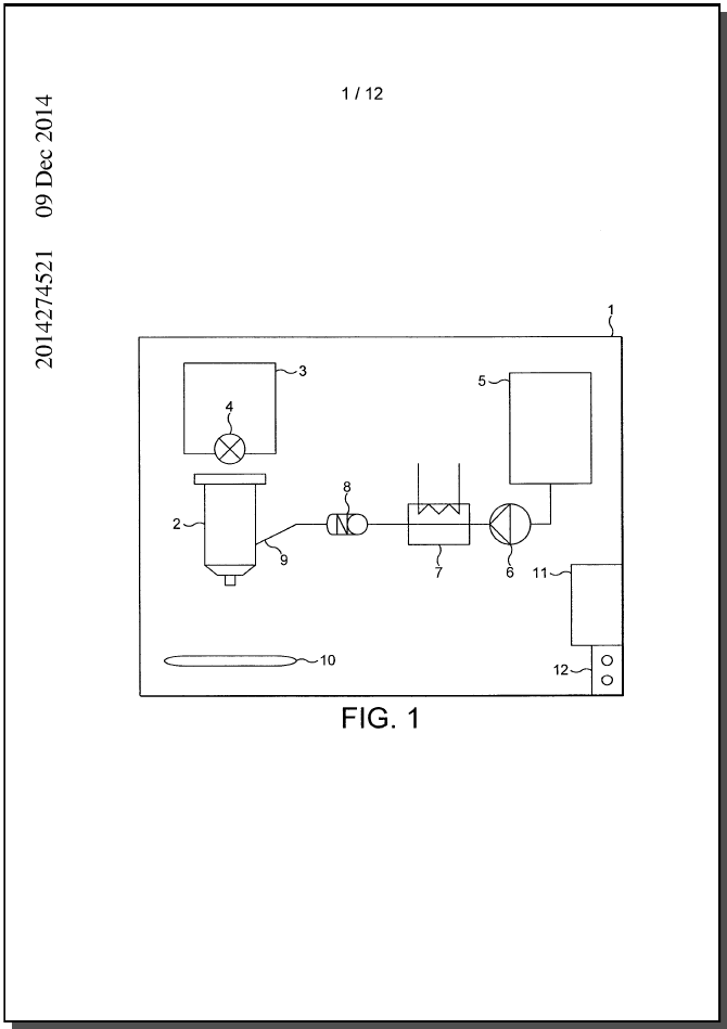
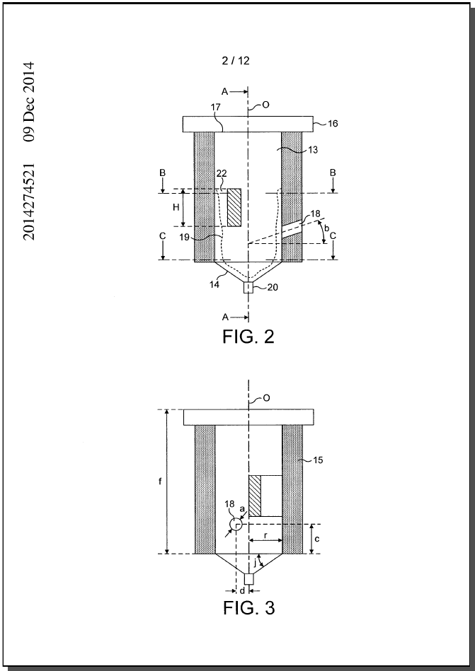
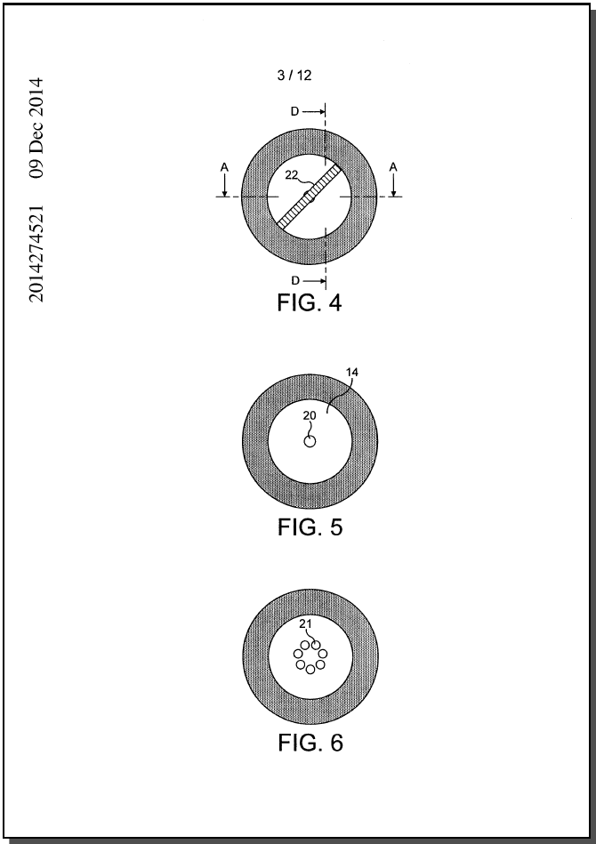
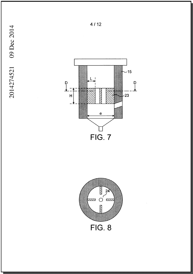
- NESTEC SA [CH]; NESTEC SA
- 분류
- Classification: - internationale A47J31/40 - coopérative
특허 패밀리 공개번호
프로젝트 이미지
설명
[0001] - 1 Device and method for producing a frothed liquid from soluble ingredients and diluent
[0001] The invention relates to a device for producing a frothed liquid in a chamber opened to the atmospheric pressure in particular using a jet of diluent to dissolve soluble ingredient or liquid concentrate and froth it into a frothed liquid. The invention further relates to a beverage production apparatus comprising such a device. The invention also relates to a method for dissolving a powder and producing a frothed liquid using a jet of diluent to dissolve soluble ingredient and froth it into a frothed liquid.
[0002] Beverage production apparatuses exist for producing frothed beverage liquids that utilize a diluent for dissolving a soluble ingredient such as coffee powder. The known systems typically utilize a mechanical high-speed rotating element such as a whipper to produce shear forces in the liquid enabling to properly dissolve the powder and produce a satisfying amount of froth.
[0003] Any discussion of the prior art throughout the specification should in no way be considered as an admission that such prior art is widely known or forms part of common general knowledge in the field.
[0004] For instance, patent applications WO 03/068039 and EP 1 639 924 relate to rotary mechanical solutions to improve frothing of liquid from a mixture of soluble ingredients and diluent.
[0005] These solutions have disadvantages in that they are noisy, involve a higher mechanical complexity and additional production costs with the need for a propelling element such as an electrical motor. Such a solution requires also more frequent cleaning or rinsing.
[0006] Therefore, these solutions using pressure prove to be not very appropriate for making a performing, low cost, noiseless and hygienic beverage producing apparatus adapted in particular for the retail channel like household small coffee appliances.
[0007] Whipperless solutions exist to provide a frothed liquid from soluble ingredient, in particular, in portioned packages such as capsules or pods. Typically, in these known solutions, a diluent is injected under pressure in a substantially closed chamber and is forced -2 under pressure to pass through a perforated membrane or a filter to create a pressure drop and shear forces to form the frothed liquid. Although these solutions are working perfectly well, they are also complex and costly to implement because of the need to ensure a pressure tight chamber during brewing or dissolution of the ingredient. Furthermore, beverage systems using portioned packages have the disadvantage to produce packaging wastes.
[0008] For instance, WO 2005/020769 Al relates to a method and device for the preparation of a food product by injection of a liquid through a capsule containing a food substance which is soluble and/or for extraction, whereby the liquid is injected from at least one injection point such as to generate a turbulent movement of injected liquid within the capsule thus causing brewing. As mentioned, this solution requires the capsule to be entirely filled with water until a certain pressure is built up inside the capsule in order for the diluent and beverage substance to mix together and provide a frothed beverage. Another issue is that the capsule remains full of liquid when the pressure in the capsule drops. Therefore, entire draining of the capsule is not possible.
[0009] WO 02/087400 relates to a method for preparation of a foamed drink comprising a capsule containing a foamable ingredient, providing a receptacle positioned to collect fluid escaping from the capsule, injecting liquid into the capsule to mix with the foamable ingredient, allowing the foamable ingredient mixed with the liquid to escape from the capsule into the receptacle; followed by injecting further the liquid into the receptacle in a jet having a diameter of from about 0.5 to 2 mm to produce a foamed liquid in the receptacle. However, this method has the disadvantage to require two distinct foaming steps performed respectively in the capsule and in a receptacle.
[0010] There is a need for a simpler, hygienic, and low cost solution enabling to produce a frothed liquid from the combination of a diluent and soluble ingredient or liquid concentrate and without involving the use of a pressurized chamber or motor-driven whipping means and without providing solid residues.
[0011] It is an object of the present invention to overcome or ameliorate at least one of the disadvantages of the prior art, or to provide a useful alternative.
[0012] -3
[0012] According to a first aspect, the present invention provides a device (2) for producing a frothed liquid comprising : - a chamber (13) opened to atmosphere with a transverse bottom wall (14) and a longitudinal upward wall (15), - at least one diluent inlet (18), - at least one liquid delivery outlet (20, 21), characterized in that the diluent inlet (18) is provided through the upward wall (15) and is dimensioned and oriented for directing a jet of diluent in the chamber (13), the at least one liquid delivery outlet (20) is configured in the bottom wall (14) for enabling liquid to rise up along the side of the upward wall (15) by the jet of diluent entering the chamber as a result of the direction and dimension of the diluent inlet in the chamber.
[0013] Unless the context clearly requires otherwise, throughout the description and the claims, the words "comprise", "comprising", and the like are to be construed in an inclusive sense as opposed to an exclusive or exhaustive sense; that is to say, in the sense of "including, but not limited to".
[0014] According to a second aspect, the present invention provides a device for producing a frothed liquid, said device comprising: - a chamber having a transverse bottom wall, a longitudinal upward wall and an upward central opening, - at least one diluent inlet, - at least one liquid delivery outlet disposed in the bottom wall, wherein the diluent inlet is provided through the upward wall and is dimensioned and oriented for directing a jet of diluent into the chamber, and wherein the at least one liquid delivery outlet and the direction and the dimension of the diluent inlet are configured for enabling liquid to rise up along the side of the upward wall to be impacted by the jet of diluent entering the chamber.
청구항
- 1.Device (2) for producing a frothed liquid comprising - a chamber (13) opened to atmosphere with a transverse bottom wall (14) and a longitudinal upward wall (15), - at least one diluent inlet (18), - at least one liquid delivery outlet (20, 21), characterized in that the diluent inlet (18) is provided through the upward wall (15) and is dimensioned and oriented for directing a jet of diluent in the chamber (13), the at least one liquid delivery outlet (20) is configured in the bottom wall (14) for enabling liquid to rise up along the side of the upward wall (15) by the jet of diluent entering the chamber as a result of the direction and dimension of the diluent inlet in the chamber.2.Device according to claim 1, characterized in that the total surface area of the liquid delivery outlet(s) (20, 21) is determined so that the evacuation flow rate by gravity of the liquid through the outlet(s) (20, 21) is lower than the filling flow rate of the chamber in diluent through the diluent inlet (18).3.Device according to claim 1 or 2, characterized in that a single liquid delivery outlet (20) is provided in the bottom wall having a cross section smaller than.4.6 mm.5.6.Device according to claim 1 or 2, characterized in that a plurality of liquid delivery outlets (21) is provided in the bottom wall wherein each individual outlet having a cross section smaller than.7.52 mm.8.9.Device according to any one of claims 1 to 4, characterized in that the liquid delivery outlet(s) (20, 21) is (are) provided in the centre or at the immediate vicinity of the centre of the bottom wall.10.Device according to any one of claims 1 to 5, characterized in that the bottom wall comprises at least one liquid delivery outlet closed by an openable valve using external control means for delaying the liquid delivery from the outlet.11.Device according to any of the preceding claims, characterized in that the diluent inlet (18) has a diameter comprised between.12.2 and 1 mm.- 2.13.Device according to any of the preceding claims, characterized in that the diluent inlet (18) is oriented along a direction inside the chamber which is offset relative to the longitudinal central axis (0) of the chamber.14.Device according to claim 78 characterized in that the diluent inlet is oriented in a direction so that the ratio of the orthogonal distance "d" to the radius "r" of the chamber is comprised between.15.2 and.16.17.18.Device according to any of the preceding claims, characterized in that the diluent inlet (18) is inclined downwardly in direction of the bottom wall a certain angle (b) relative to the transversal plane.19.Device according to claim 10, characterized in that the angle (b) relative to transversal plane of the chamber is comprised between 5 and 30 degrees.20.Device according to any of the preceding claims, characterized in that it comprises two diluent inlets placed at different heights of the chamber upward wall.21.Device according to any of the preceding claims, characterized in that it comprises at least one baffle means placed at least partially across the chamber.22.Device according to claim 13, characterized in that at least one baffle means (22) is placed above the diluent inlet (18).23.Device according to claim 14, characterized in that it comprises a plurality of baffles vertically oriented along and/or inclined relative to the longitudinal central axis.24.Device according to claim 13, characterized in that at least one baffle means face at least one diluent inlet (18).25.Device according to Claim 16, characterized in that said baffle means are placed totally across the chamber and comprise orifices.26.Device according to Claim 17, characterized in that said baffle means are a sieve.- 2.27.Device according to Claim 18, characterized in that the sieve presents a number of eyes per cm' comprised between 50 and.28.29.Device according to Claims 16 to 19, characterized in that it comprises two diluent inlets, one diluent inlet being placed above the baffle means.30.Device according to any of the preceding claims, characterized in that the chamber comprises a conduit placed at the top of the chamber said conduit providing a liquid outlet allowing liquid to exit the chamber after the liquid has exceeded the chamber capacity.31.Device according to any of the preceding claims, characterized in that it forms a disposable or recyclable cartridge which contains an amount of soluble ingredient.32.Device according to claim 22, characterized in that the diluent inlet and air aperture are hermetically closed by at least one airtight removable membrane.33.Beverage production apparatus comprising the device according to any of the preceding claims comprising diluent feed means which is connectable to the diluent inlet.34.Method for producing a frothed liquid in a beverage production apparatus comprising: - providing a chamber (13) with a transverse bottom wall (14) and a longitudinal upward wall (15), - dosing the chamber (13) with soluble ingredient, - feeding a diluent through a diluent inlet (18) to create a jet of diluent in the chamber (13) and mix the diluent with said soluble ingredient to dissolve it into a liquid, - controlling the liquid flow delivered out of the chamber in such a manner that the liquid can rise up a certain level along the side of the upward wall when diluent is fed in the chamber and for the liquid to form a sheared surface of liquid which is energically impacted, as a result of the direction and dimension of the diluent inlet in the chamber, by the jet of diluent, - stopping the diluent intake inside the chamber and draining the frothed liquid from the chamber at least one outlet.35.Method according to claim 25, characterized in that controlling the liquid flow delivered out of the chamber comprises delaying the liquid flow out of the chamber relative to the intake of diluent inside the chamber.- 2.36.Method according to claims 25 or 24, characterized in that feeding the diluent in the chamber comprises passing the diluent through a diluent inlet and orienting the diluent jet in a direction inside the chamber which is offset relative to the longitudinal central axis of the chamber.37.Method according to claim 27, characterized in that the oriented diluent jet is thrown through a sieve placed across the chamber.38.Method according to any one of claims 24 to 28, characterized in that a soluble coffee ingredient is dosed in the chamber.39.Method according to any one of claims 24 to 29, characterized in that it comprises further rinsing the chamber by passing diluent through the diluent inlet after draining of the frothed liquid in the chamber and further draining the rinsing liquid.40.A device for producing a frothed liquid, said device comprising: - a chamber having a transverse bottom wall, a longitudinal upward wall and an upward central opening, - at least one diluent inlet, - at least one liquid delivery outlet disposed in the bottom wall, wherein the diluent inlet is provided through the upward wall and is dimensioned and oriented for directing a jet of diluent into the chamber, and wherein the at least one liquid delivery outlet and the direction and the dimension of the diluent inlet are configured for enabling liquid to rise up along the side of the upward wall to be impacted by the jet of diluent entering the chamber.41.A device according to claim 31, wherein the total surface area of the liquid delivery outlet(s) is determined so that the evacuation flow rate by gravity of the liquid through the outlet(s) is lower than the filling flow rate of the chamber in diluent through the diluent inlet.42.A device according to claim 31 or 32, wherein a single liquid delivery outlet is provided in the bottom wall having a cross section smaller than.43.6 mm.44.45.A device according to claim 31 or 32, wherein a plurality of liquid delivery outlets is provided in the bottom wall wherein each individual outlet having a cross section smaller than.46.52 mm 2 - 2.47.A device according to any one of claims 31 to 34, wherein the liquid delivery outlet(s) is (are) provided in the centre or at the immediate vicinity of the centre of the bottom wall.48.A device according to any one of claims 31 to 35, wherein the bottom wall comprises at least one liquid delivery outlet closed by an openable valve using external control means for delaying the liquid delivery from the outlet.49.A device according to any one of claims 31 to 36, wherein the diluent inlet has a diameter of between.50.2 and 1 mm.51.A device according to any one of claims 31 to 37, wherein the diluent inlet is oriented along a direction inside the chamber which is offset relative to the longitudinal central axis (0) of the chamber.52.A device according to any one of claims 31 to 38, wherein the diluent inlet is orientated such that the respective jet of diluent encourages centrifugal circulation encouraging a layer of circulating liquid to rise up along the side of the upward wall.53.A device according to claim 39, wherein the rising liquid intercepts the jet of diluent thereby generating shear forces in the liquid.54.A device according to claim 38 wherein the diluent inlet is oriented in a direction so that the ratio of the orthogonal distance "d" to the radius "r" of the chamber is between.55.2 and.56.57.58.A device according to any one of claims 31 to 41, wherein the diluent inlet is inclined downwardly in direction of the bottom wall a certain angle (b) relative to the transversal plane.59.A device according to claim 42, wherein the angle (b) relative to transversal plane of the chamber is between 5 and 30 degrees.60.A device according to any one of claims 31 to 43, comprising two diluent inlets placed at different heights of the chamber upward wall.61.A device according to any one of claims 31 to 44, further comprising at least one baffle means placed at least partially across the chamber.- 2.62.A device according to claim 41, wherein at least one baffle means is placed above the diluent inlet.63.A device according to claim 42, comprising a plurality of baffles vertically oriented along and/or inclined relative to the longitudinal central axis.64.A device according to claim 41, wherein at least one baffle means face at least one diluent inlet.65.A device according to Claim 48, wherein said baffle means are placed totally across the chamber and comprise orifices.66.A device according to Claim 45, wherein said baffle means are a sieve.67.A device according to Claim 50, wherein the sieve presents a number of apertures per cm 2 of between 50 and.68.69.A device according to any one of Claims 48 to 51, comprising two diluent inlets, one diluent inlet being placed above the baffle means.70.A device according to any one of claims 31 to 52, wherein the chamber comprises a conduit placed at the top of the chamber said conduit providing a liquid outlet allowing liquid to exit the chamber after the liquid has exceeded the chamber capacity.71.A device according to any one of claims 31 to 53, wherein the device forms a disposable or recyclable cartridge which contains an amount of soluble ingredient.72.A device according to claim 54, wherein the diluent inlet and air aperture are hermetically closed by at least one airtight removable membrane.73.A device according to claim 31, wherein the diluent inlet is situated at a distance closer to the base of the bottom wall than to the central opening.74.A beverage production apparatus comprising the device according to any of claims 31 to 57comprising diluent feed means which is connectable to the diluent inlet.- 2.75.A method for producing a frothed liquid in a beverage production apparatus, said method comprising: - providing a chamber with a transverse bottom wall and a longitudinal upward wall, - dosing the chamber with soluble ingredient, - feeding a diluent through a diluent inlet to create a jet of diluent in the chamber and mix the diluent with said soluble ingredient to dissolve it into a liquid, - controlling the liquid flow delivered out of the chamber in such a manner that the liquid can rise up along the side of the upward wall when diluent is fed in the chamber and for the liquid to form a sheared surface of liquid which is impacted, as a result of the direction and dimension of the diluent inlet in the chamber, by the jet of diluent, - stopping the diluent intake inside the chamber and draining the frothed liquid from the at least one outlet of the chamber.76.A method according to claim 58, wherein controlling the liquid flow delivered out of the chamber comprises delaying the liquid flow out of the chamber relative to the intake of diluent inside the chamber.77.A method according to claims 58 or 59, wherein feeding the diluent in the chamber comprises passing the diluent through a diluent inlet and orienting the diluent jet in a direction inside the chamber which is offset relative to the longitudinal central axis of the chamber.78.A method according to claim 60, wherein the oriented diluent jet is thrown through a sieve placed across the chamber.79.A method according to any one of claims 58 to 62, wherein a soluble coffee ingredient is dosed in the chamber.80.A method according to any one of claims 58 to 62, further comprising rinsing the chamber by passing diluent through the diluent inlet after draining of the frothed liquid in the chamber and further draining the rinsing liquid.