


US2015342657 (A1)
CONJUNTO DE FIJACIÓN ÓSEA.
Un sistema de fijación ósea incluye al menos un miembro de fijación ósea y un instrumento de fijación ósea. El miembro de fijación ósea incluye una correa y un mecanismo de bloqueo. La correa se puede tirar a través del mecanismo de bloqueo para formar un bucle alrededor de un hueso objetivo para asegurar el primer y segundo segmento óseo en una configuración comprimida aproximada. El instrumento de fijación ósea está configurado para aplicar tensión al bucle alrededor del hueso objetivo. El instrumento de fijación incluye un conjunto de tensión que está configurado para asegurar un extremo libre del miembro de fijación ósea al instrumento de fijación. El conjunto de tensión está configurado además para tirar del extremo libre con el fin de aumentar la tensión en el bucle mientras la tensión en el bucle es menor que una tensión seleccionada. El conjunto de tensión no puede aumentar más la tensión en el miembro de fijación ósea una vez que la tensión en el miembro de fijación ósea ha alcanzado la tensión seleccionada. El instrumento de fijación incluye además un conjunto cortador que está configurado para cortar el extremo libre del miembro de fijación ósea para separar el extremo libre del bucle.
- Publicación
- US2015342657 (A1)
- Fecha de publicación
- 2015-12-03
- Fecha de prioridad
- 2014-05-30
- Inventores
- THULIEZ JEAN-LUC [CH]; VOISARD CYRIL [CH]; OBLIGER NICOLAS [FR]; MOOTIEN AZAGEN [FR]; CROZIER ETIENNE [CH]
- Solicitantes
- DEPUY SYNTHES PRODUCTS INC [US]
- Clasificación
- Classification: - internationale A61B17/58; A61B17/60; A61B17/82; A61B17/84; A61B17/88; A61F2/00 - coopérative A61B17/823 (EP, CN, US); A61B17/842 (EP, CN, US); A61B17/8861 (EP, CN, US); A61B17/8863 (EP, CN, US); A61B17/8869 (EP, CN, US); A61B17/8872 (EP, CN, US)
Publicaciones de la familia
Proyectos relacionados
Imágenes del proyecto
Descripción
CROSS-REFERENCE TO RELATED APPLICATIONS
[0001] This claims the benefit of U.S. Patent Application Ser. No. 62/005,552 filed May 30, 2014, the disclosure of which is hereby incorporated by reference as if set forth in its entirety herein. BACKGROUND
[0002] In order to provide access to certain internal anatomy, such as the heart during an open heart procedure, midline sternotomies are typically performed. A midline sternotomy creates a cut substantially along the midline of the sternum, thereby dividing the ribcage into two halves and allowing the surgeon to move the ribcage so as to provide access to the heart. Upon completion of the open heart procedure, it is desired to approximate and compress the sternum, and rigidly maintain the sternal halves in their approximated position relative to each other so that the sterna halves are restricted from moving with respect to each other to promote bone fusion in the weeks following the surgical procedure.
[0003] During normal anatomical function, for instance during respiration, body movement, and carrying of objects, forces can be generated that act on the sternum. One conventional system sternal fixation assembly includes stainless steel wires that are placed either parasternally (around the sternum) or transsternally (through the sternum bone) using a cutting needle that is attached to the wire, and subsequently twisted to tighten the wire against the sternum. However, the twisting generates tensile forces onto the wires that tend to weaken the wire, which can result in breakage both during the closure or post-operatively. Furthermore, this type of system relies on the experience of the surgeon when tightening the wires. If the wires are not tightened enough, the sternal compression can be compromised. If the wires are tightened too much, the wire can cut into or through the sternum and/or can break. SUMMARY
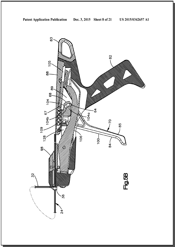
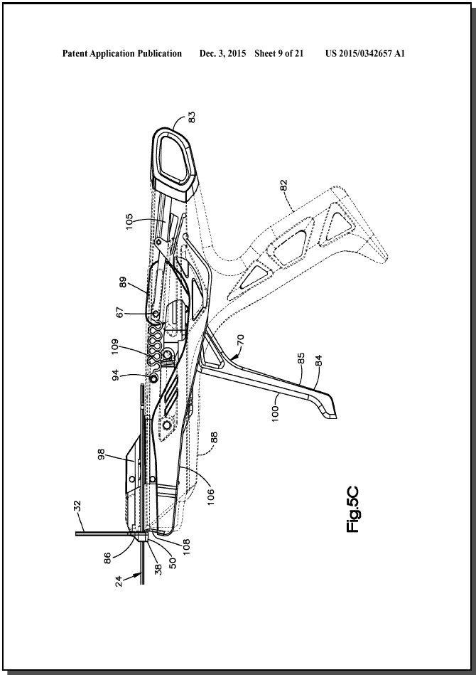
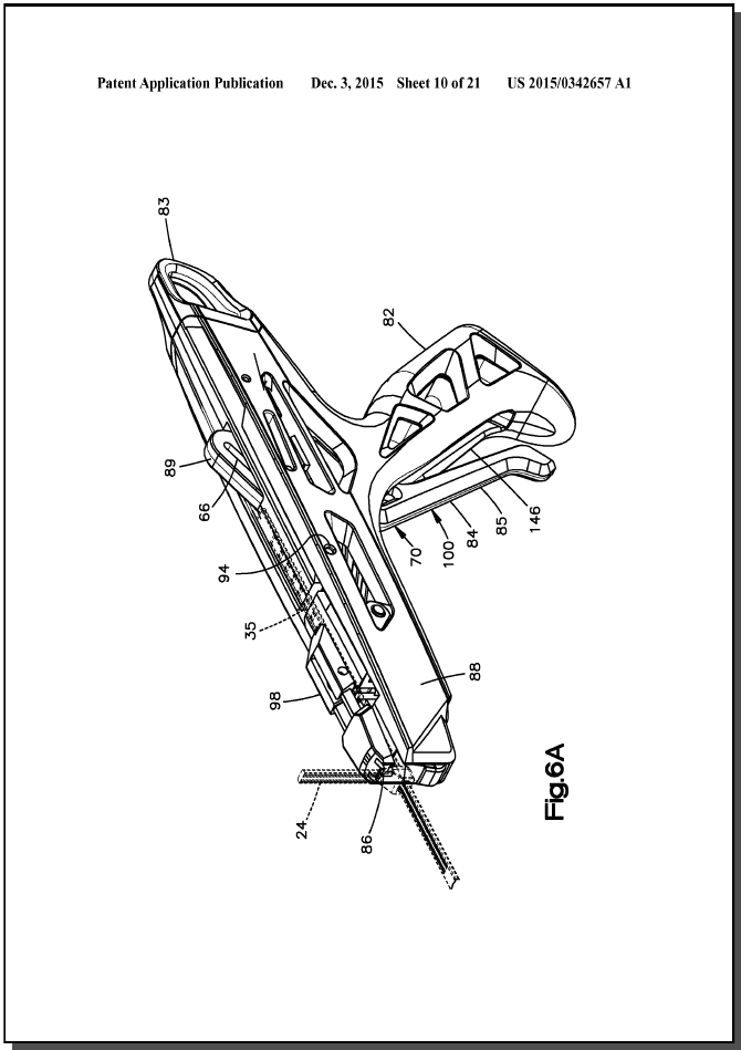
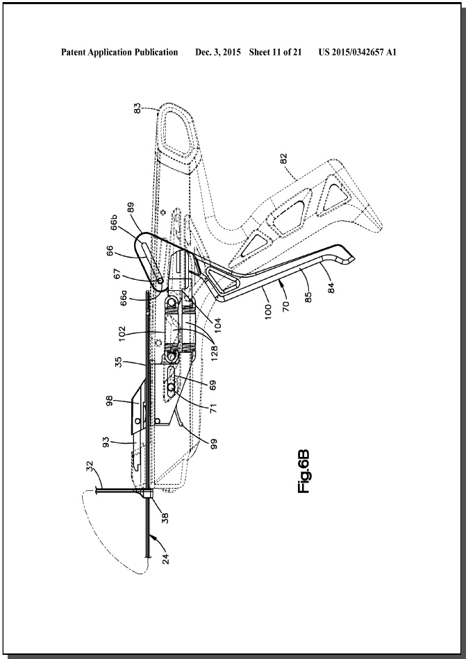
[0004] In accordance with one embodiment, a bone fixation instrument has a front end and a rear end spaced from the front end in a rearward direction. The bone fixation instrument can be configured to apply tension to a bone fixation member so as to tighten the bone fixation member about a target bone. The bone fixation instrument can include a grip configured to attach to a free end of the bone fixation member. The bone fixation instrument can further include a traveler that supports the grip such that as the traveler moves in the rearward direction, the grip moves along with the traveler in the rearward direction so as to increase tension in the bone fixation member when the grip is attached to the bone fixation member. The bone fixation instrument can further include a cutter arm that carries a cutter blade and is configured to move the cutter blade to a cutting position whereby the cutter blade severs the free end of the bone fixation member when the grip is attached to the bone fixation member. The bone fixation instrument can further include an actuator configured to be selectively independently coupled to the traveler and the cutter arm. The bone fixation instrument can further include a toggle member that is movable between a first and a second position. When the toggle member is in the first position, the bone fixation instrument can be in a tensioning mode whereby movement of the actuator causes the traveler to move in the rearward direction thereby increasing the tension in the bone fixation member when the grip is attached to the bone fixation member. When the toggle member is in the second position, the bone fixation instrument can be in a cutting mode whereby movement of the actuator causes the cutter arm to move the cutter blade to the cutting position. BRIEF DESCRIPTION OF THE DRAWINGS
[0005] The foregoing summary, as well as the following detailed description of the preferred embodiments of the application, will be better understood when read in conjunction with the appended drawings. For the purposes of illustrating the present disclosure, there is shown in the drawings preferred embodiments. It should be understood, however, that the application is not limited to the specific embodiments and methods disclosed, and reference is made to the claims for that purpose. In the drawings:
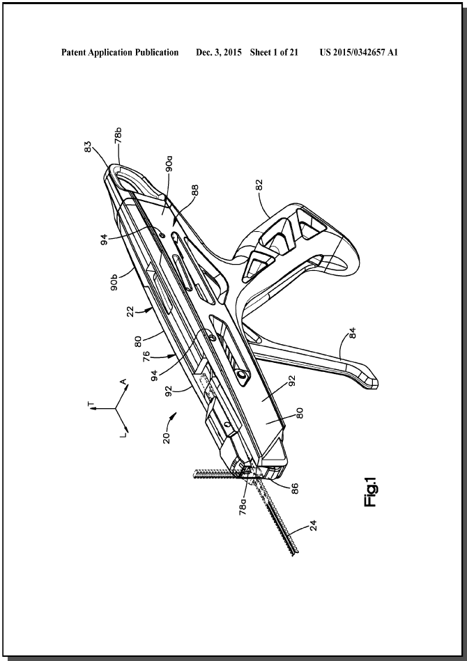
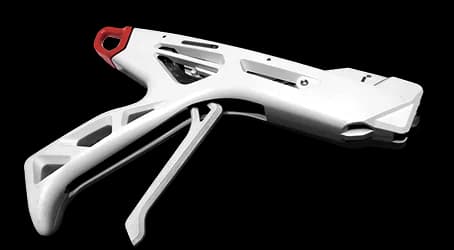
[0006] FIG. 1 is a perspective view of a bone fixation assembly constructed in accordance with one embodiment, including a bone fixation instrument and a bone fixation member received by the bone fixation member;
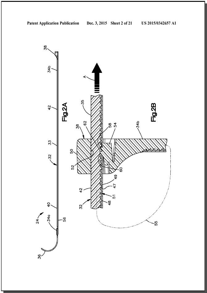
[0007] FIG. 2A is a perspective view of the bone fixation member illustrated in FIG. 1, including a body and a locking member, showing the bone fixation member in an initial configuration;
[0008] FIG. 2B is an enlarged perspective view of a portion of the bone fixation member illustrated in FIG. 2A, showing the body inserted through the locking member so as to secure the bone fixation member about an underlying bone;
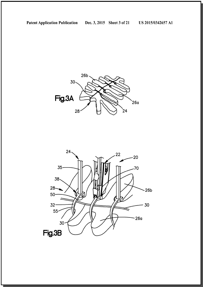
[0009] FIG. 3A is a perspective view of a plurality of the bone fixation members illustrated in FIG. 2A shown tightened about a target bone and cut;
[0010] FIG. 3B is a perspective view of the bone fixation instrument illustrated in FIG. 1 operatively coupled to and tightening one of a plurality of the bone fixation members illustrated in FIG. 3A;
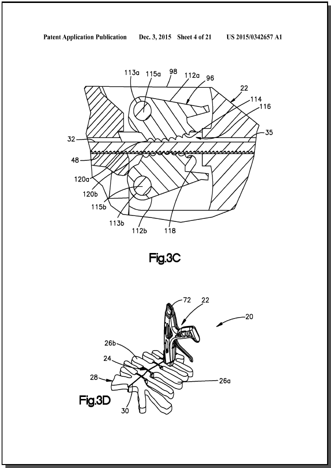
[0011] FIG. 3C is an enlarged sectional side elevation view of a grip of the bone fixation instrument as illustrated in FIG. 3B, shown receiving a free end of the bone fixation member;
[0012] FIG. 3D is a perspective view of the bone fixation instrument illustrated in FIG. 1 operatively coupled to and cutting one of the tightened bone fixation members illustrated in FIG. 3B;
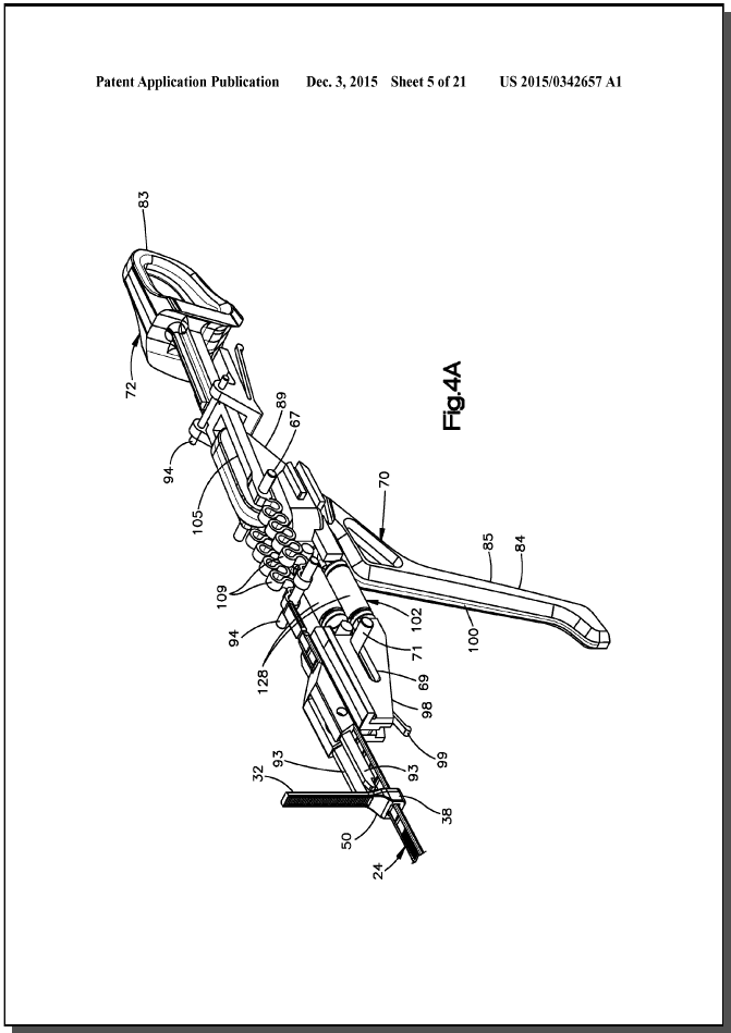
[0013] FIG. 4A is a perspective view of the bone fixation instrument illustrated in FIG. 1, with portions removed to illustrate internal components including a tension assembly and a cutter assembly;
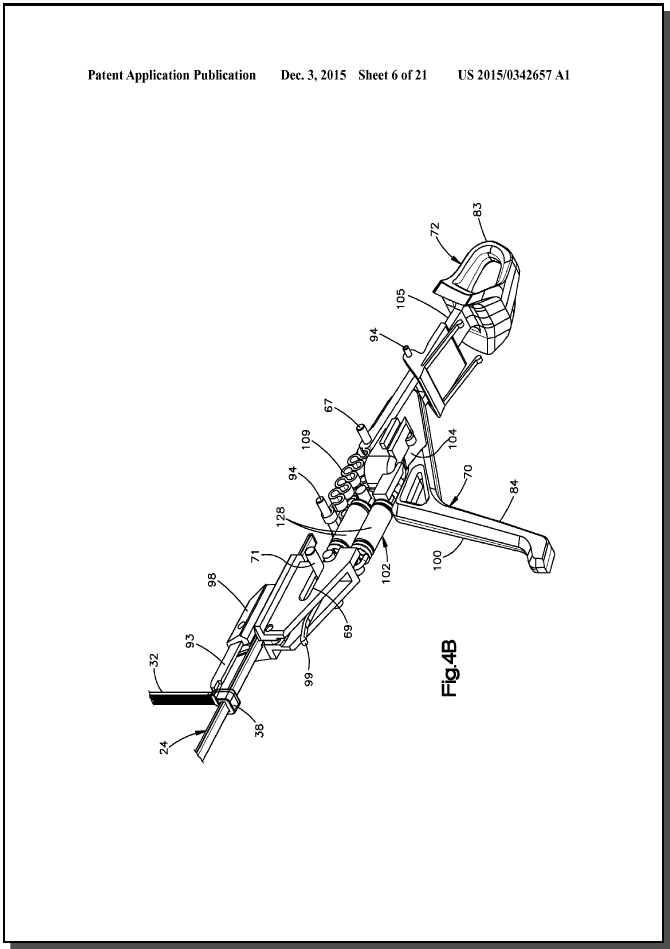
[0014] FIG. 4B is a another perspective view of the bone fixation instrument illustrated in FIG. 4A;
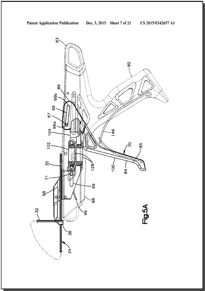
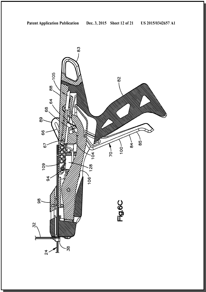
[0015] FIG. 5A is a side elevation view of the bone fixation instrument illustrated in FIG. 1, showing the tension assembly in a neutral position;
Reivindicaciones
- 1. What is claimed:
- 1. A bone fixation instrument having a front end and a rear end spaced from the front end in a rearward direction, the bone fixation instrument configured to apply tension to a bone fixation member so as to tighten the bone fixation member about a target bone, the bone fixation instrument comprising: a grip configured to attach to a free end of the bone fixation member;a traveler that supports the grip such that as the traveler moves in the rearward direction, the grip moves along with the traveler in the rearward direction so as to increase tension in the bone fixation member when the grip is attached to the bone fixation member;a cutter arm that carries a cutter blade and is configured to move the cutter blade to a cutting position whereby the cutter blade severs the free end of the bone fixation member when the grip is attached to the bone fixation member;an actuator configured to be selectively independently coupled to the traveler and the cutter arm; anda toggle member movable between a first and a second position, wherein 1) when the toggle member is in the first position, the bone fixation instrument is in a tensioning mode whereby movement of the actuator causes the traveler to move in the rearward direction thereby increasing the tension in the bone fixation member when the grip is attached to the bone fixation member, and 2) when the toggle member is in the second position, the bone fixation instrument is in a cutting mode whereby movement of the actuator causes the cutter arm to move the cutter blade to the cutting position.
- 2. The bone fixation instrument as recited in claim 1, wherein when the bone fixation instrument is in the tensioning mode and the grip is attached to the bone fixation member, movement of the actuator causes the traveler to move in the rearward direction until the tension in the bone fixation member reaches a predetermined tension.
- 3. The bone fixation instrument as recited in claim 2, further comprising a force transfer member and a tension limiter coupled between the tension limiter and the traveler, wherein the force transfer member is coupled to the actuator when the bone fixation member is in the tensioning mode, and decoupled from the actuator when the bone fixation member is in the cutting mode.
- 4. The bone fixation instrument as recited in claim 3, wherein the deformation of the tension limiter causes the traveler to move rearward in response to movement of the actuator toward the second position when the tension in the bone fixation member is less than a predetermined tension, and does not cause the traveler to move in the rearward direction in response to movement of the actuator toward the second position when the tension in the bone fixation member reaches the predetermined tension.
- 5. The bone fixation instrument as recited in claim 3, wherein the tension limiter further causes the traveler to move in a forward direction opposite the rearward direction when the actuator moves from the second position toward the first position while the bone fixation instrument is in the tensioning mode.
- 6. The bone fixation instrument as recited in claim 3, wherein the tension limiter comprises a spring member connected between the actuator and the traveler, wherein movement of the actuator causes the spring member to flex and bias the traveler rearward under a biasing force when the bone fixation instrument is in the tensioning mode.
- 7. The bone fixation instrument as recited in claim 6, wherein the traveler moves rearward when the biasing force is greater than the tension in the bone fixation member.
- 8. The bone fixation instrument as recited in claim 7, wherein the traveler remains stationary when the biasing force is not greater than the tension in the bone fixation member.
- 9. The bone fixation instrument as recited in claim 5, wherein the grip interlocks with the free end of the bone fixation member while the grip moves in the rearward direction, and the grip rides along the free end of the bone fixation member when the grip moves in the forward direction.
- 10. The bone fixation instrument as recited in claim 1, wherein the actuator moves about a first axis when the bone fixation instrument is in the tensioning mode, and the actuator moves about a second axis that is spaced from the first axis when the bone fixation instrument is in the cutting mode.
- 11. The bone fixation instrument as recited in claim 10, wherein the actuator defines a slot that receives a pivot pin, wherein the pivot pin is in a first position when the bone fixation instrument is in the tensioning mode, and the pivot pin is in a second position spaced from the first position in the rearward direction when the bone fixation instrument is in the cutting mode.
- 12. The bone fixation instrument as recited in claim 1, wherein movement of the toggle member to the second position causes the actuator to abut the cutter arm when the bone fixation instrument is in the cutting mode.
- 13. The bone fixation instrument as recited in claim 1, wherein the actuator defines an actuation pin that is received in a slot of the force transfer member when the bone fixation instrument is in the tensioning mode, and is removed from the slot when the bone fixation instrument is in the cutting mode.
- 14. The bone fixation instrument as recited in claim 13, wherein the actuation pin abuts the cutting member when the bone fixation instrument is in the cutting mode.
- 15. The bone fixation instrument as recited in claim 14, wherein movement of the actuator causes the actuation pin to drive the cutting member to move the cutting blade to the cutting position.
- 16. A bone fixation instrument having a front end and a rear end spaced from the front end in a rearward direction, the bone fixation instrument configured to apply tension to a bone fixation member so as to tighten the bone fixation member about a target bone, the bone fixation instrument comprising: a grip configured to attach to a free end of the bone fixation member;a traveler that supports the grip such that as the traveler moves in the rearward direction, the grip moves along with the traveler in the rearward direction so as to increase tension in the bone fixation member when the grip is attached to the bone fixation member;a cutter arm that carries a cutter blade, the cutter arm configured to move the cutter blade to a cutting position whereby the cutter blade severs the free end of the bone fixation member when the grip is attached to the bone fixation member;an actuator configured to selectively pivot about a first pivot axis and a second pivot axis that is spaced from the first pivot axis, such that when the actuator pivots about the first pivot axis, the actuator causes a force to be applied to the traveler in the rearward direction, and when the actuator pivots about the second pivot axis, the actuator causes a force to be applied to the cutter member, thereby causing the cutter member to move the cutting blade to the cutting position.
- 17. The bone fixation instrument as recited in claim 16, wherein the actuator is configured to be selectively independently coupled to the traveler and the cutter arm.
- 18. The bone fixation instrument as recited in claim 16, wherein the actuator is coupled to the traveler when the actuator pivots about the first pivot axis, and the actuator is coupled to the cutter arm when the actuator pivots about the second pivot axis.
- 19. The bone fixation instrument as recited in claim 16, wherein the actuator is decoupled from the cutter arm when the actuator pivots about the first pivot axis, and the actuator is decoupled from the traveler when the actuator pivots about the second pivot axis.
- 20. The bone fixation instrument as recited in claim 16, further comprising a toggle member movable between a first and a second position, wherein 1) when the toggle member is in the first position, the bone fixation instrument is in a tensioning mode whereby movement of the actuator about the first pivot axis causes the traveler to move in the rearward direction until the tension in the bone fixation member reaches a predetermined tension when the grip is attached to the bone fixation member, and 2) when the toggle member is in the second position, the bone fixation instrument is in a cutting mode whereby movement of the actuator about the second pivot axis causes the cutter arm to move the cutter blade to the cutting position.