


US2010173057 (A1)
DISPOSITIVO Y MÉTODO PARA PRODUCIR UN LÍQUIDO ESPUMADO A PARTIR DE INGREDIENTES SOLUBLES Y DILUYENTE.
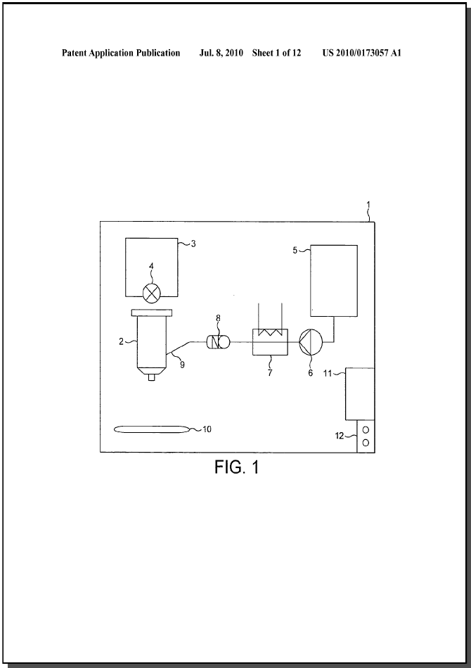
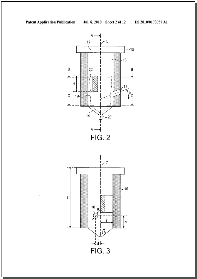
Dispositivo para producir un líquido espumoso que comprende una cámara 13 abierta a la atmósfera con una pared inferior transversal 14 y una pared longitudinal hacia arriba 15, al menos una entrada de diluyente 18, al menos una salida de suministro de líquido 20, en donde la entrada de diluyente se proporciona a través de la pared hacia arriba y está dimensionada y orientada para dirigir un chorro delgado de diluyente en la cámara, y en donde la al menos una salida de suministro de líquido está configurada en la pared inferior para que el líquido suba a lo largo del costado. de la pared superior por el chorro de diluyente que entra en la cámara como resultado de la dirección y dimensión de la entrada de diluyente en la cámara.
- Publicación
- US2010173057 (A1)
- Fecha de publicación
- 2010-07-08
- Fecha de prioridad
- 2006-12-11
- Inventores
- THULIEZ JEAN-LUC [CH]; DOGAN NIHAN [CH]; BEAUSIRE CEDRIC [CH]; KISSLING IWAN [CH]; HAMEL DAVID [CH]; BERNHARDSGRUETTER RAPHAEL [CH]; GUGERLI RAPHAEL [CH]; HARRISON DAVID J [US]
- Solicitantes
- THULIEZ JEAN-LUC [CH]; DOGAN NIHAN [CH]; BEAUSIRE CEDRIC [CH]; KISSLING IWAN [CH]; HAMEL DAVID [CH]; NESTEC SA [CH]; BERNHARDSGRUETTER RAPHAEL [CH]; GUGERLI RAPHAEL [CH]; HARRISON DAVID J [US]
- Clasificación
- Classification: - internationale A23L1/00; A23L2/54; A47J31/40; B01F3/04 - coopérative A23F5/262 (EP, US); A23L2/54 (US); A23V2002/00 (US); A47J31/401 (EP, US); A47J31/404 (US); A47J31/407 (US); A47J31/46 (EP, US); A47J31/462 (US); B65D85/8049 (EP, US); B65D85/8052 (EP, US)
Publicaciones de la familia
Proyectos relacionados
Imágenes del proyecto

Descripción
[0001] The invention relates to a device for producing a frothed liquid in a chamber opened to the atmospheric pressure in particular using a jet of diluent to dissolve soluble ingredient or liquid concentrate and froth it into a frothed liquid. The invention further relates to a beverage production apparatus comprising such a device. The invention also relates to a method for dissolving a powder and producing a frothed liquid using a jet of diluent to dissolve soluble ingredient and froth it into a frothed liquid.
[0002] Beverage production apparatuses exist for producing frothed beverage liquids that utilize a diluent for dissolving a soluble ingredient such as coffee powder. The known systems typically utilize a mechanical high-speed rotating element such as a whipper to produce shear forces in the liquid enabling to properly dissolve the powder and produce a satisfying amount of froth.
[0003] For instance, patent applications WO 03/068039 and EP 1 639 924 relate to rotary mechanical solutions to improve frothing of liquid from a mixture of soluble ingredients and diluent.
[0004] These solutions have disadvantages in that they are noisy, involve a higher mechanical complexity and additional production costs with the need for a propelling element such as an electrical motor. Such a solution requires also more frequent cleaning or rinsing.
[0005] Therefore, these solutions using pressure prove to be not very appropriate for making a performing, low cost, noiseless and hygienic beverage producing apparatus adapted in particular for the retail channel like household small coffee appliances.
[0006] Whipperless solutions exist to provide a frothed liquid from soluble ingredient, in particular, in portioned packages such as capsules or pods. Typically, in these known solutions, a diluent is injected under pressure in a substantially closed chamber and is forced under pressure to pass through a perforated membrane or a filter to create a pressure drop and shear forces to form the frothed liquid. Although these solutions are working perfectly well, they are also complex and costly to implement because of the need to ensure a pressure tight chamber during brewing or dissolution of the ingredient. Furthermore, beverage systems using portioned packages have the disadvantage to produce packaging wastes.
[0007] For instance, WO 2005/020769 A1 relates to a method and device for the preparation of a food product by injection of a liquid through a capsule containing a food substance which is soluble and/or for extraction, whereby the liquid is injected from at least one injection point such as to generate a turbulent movement of injected liquid within the capsule thus causing brewing. As mentioned, this solution requires the capsule to be entirely filled with water until a certain pressure is built up inside the capsule in order for the diluent and beverage substance to mix together and provide a frothed beverage. Another issue is that the capsule remains full of liquid when the pressure in the capsule drops. Therefore, entire draining of the capsule is not possible.
[0008] WO 02/087400 relates to a method for preparation of a foamed drink comprising a capsule containing a foamable ingredient, providing a receptacle positioned to collect fluid escaping from the capsule, injecting liquid into the capsule to mix with the foamable ingredient, allowing the foamable ingredient mixed with the liquid to escape from the capsule into the receptacle; followed by injecting further the liquid into the receptacle in a jet having a diameter of from about 0.5 to 2 mm to produce a foamed liquid in the receptacle. However, this method has the disadvantage to require two distinct foaming steps performed respectively in the capsule and in a receptacle.
[0009] There is a need for a simpler, hygienic, and low cost solution enabling to produce a frothed liquid from the combination of a diluent and soluble ingredient or liquid concentrate and without involving the use of a pressurized chamber or motor-driven whipping means and without providing solid residues.
[0010] The invention is based on a device comprising a chamber opened to atmospheric pressure wherein a combination of at least one jet of diluent and liquid outlet means is configured in such a manner that surfaces of circulating liquid in the chamber are submitted to high shear forces effective to dissolve a powder and produce a frothed liquid.
[0011] The result of the froth created by the device is even improved compared to mechanical whipping devices and at least comparable to pressure capsule system, however, without having the aforementioned disadvantages of any of these systems.
[0012] More particularly, the device of the invention comprises a chamber opened to atmosphere with a transverse bottom wall and a longitudinal upward wall, at least one diluent inlet and at least one liquid delivery outlet, wherein the diluent inlet is provided through the upward wall and is dimensioned and oriented for directing a jet of diluent in the chamber and the at least one liquid delivery outlet is configured in the bottom wall for enabling liquid to rise up along the side of the upward wall by the jet of diluent entering the chamber as a result of the direction and dimension of the diluent inlet in the chamber.
[0013] Therefore, according to the general principle of the invention, the chamber is designed in such a way that a layer of circulating liquid is produced that rises up along the side of the upward wall; forming a liquid surface which is submitted to important shear forces from at least one jet of diluent. A second surface of liquid can also be produced along the bottom of the chamber which is also submitted to shear forces from the jet of diluent. The layer of circulating liquid is mainly obtained by controlling the liquid flow exiting the chamber to maintain a sufficient volume of liquid in the chamber and by the configuration of the diluent inlet which must properly impact on the liquid to make it swirled and to froth it. The liquid delivery outlet(s) and the direction and the dimension of the diluent inlet are configured for enabling liquid to rise up along the side of the upward wall.
[0014] According to the invention, the diluent can be any suitable liquid adapted for dissolving a food soluble ingredient using the features and conditions of the device. A preferred diluent is hot water but other diluents such as cold water or other aqueous liquids can be utilized such as liquid milk.
[0015] The soluble ingredient can be any foamable food ingredient that dissolves and performs to produce a foamed liquid using the features and conditions of the device of the invention. A preferred ingredient is soluble coffee powder. However, other ingredients can be used in the device of the invention to provide foamed liquid such as soluble tea, dehydrated culinary ingredients and/or milk based ingredients. The device and the method of the present invention are applicable too to the dissolution and frothing of liquid concentrates with a diluent. Such liquid concentrates may be coffee, chocolate or milk concentrates.
[0016] According to the invention, the bottom wall comprises one liquid outlet or a plurality of liquid outlets. More particularly, the total surface area of the outlet(s) is determined so that the evacuation flow rate by gravity of the liquid through the outlet(s) is lower than the filling flow rate of the chamber in diluent through the diluent inlet. By lower, it is meant that the evacuation flow rate is inferior or equal to the filling flow rate. Of course, the slower evacuation of the chamber takes into account the dynamic of the fluid in the chamber. For instance, fluid can be less prone to evacuate when being maintained in a swirl motion along the side of the chamber. As a result of this configuration, a layer of liquid can be maintained in circulation in the chamber to be collided by the jet of diluent entering the chamber at least as long as diluent enters the chamber. Preferably, the outlet or plurality of outlets are in majority localized at or immediately close to the centre of the bottom wall. This configuration participates to slowing down the evacuation of the liquid out of the device. In a preferred arrangement of the device, the total cross-section of the liquid outlet is sufficiently small as to retain sufficient liquid in the chamber when diluent enters the chamber but does still provide an effective draining of the chamber by simple gravity effect. Preferably, the upward wall is substantially vertical to promote liquid draining. The device has proved to be self-cleaning in the sense that substantially no foam solid or foam residue is left in the chamber after operation. The diluent can rinse the inner surfaces of the chamber and liquid or solids residue can evacuate entirely to the outlet(s). Indeed, it is important to be able to fully drain and rinse the chamber in order to keep it clean and avoid hygiene issues. Preferably, the cross-section of a single liquid outlet is smaller than 12.6 mm<2>. The cross section of each liquid outlet in a configuration involving a plurality of outlets in the bottom wall is smaller than about 2 mm<2>, most preferably smaller than 1.54 mm<2>. It can be noticed that the cross section of the outlets is also dependent of the cross section and volume of the chamber. The relation between the cross sections is determined to ensure a control of the liquid inside the device enabling a proper dissolution and frothing by the jet of diluent.
Reivindicaciones
- 1. Device for producing a frothed liquid comprising: a chamber opened to the atmosphere having a transverse bottom wall and a longitudinal upward wall,at least one diluent inlet,at least one liquid delivery outlet,the diluent inlet is provided through the upward wall and directs a jet of diluent into the chamber,the liquid delivery outlet is configured in the bottom wall for enabling liquid to rise up along the side of the upward wall by the jet of diluent entering the chamber as a result of the direction and dimension of the diluent inlet in the chamber.
- 2. Device according to claim 1, wherein the total surface area of the liquid delivery outlet is determined so that the evacuation flow rate by gravity of the liquid through the outlet is lower than the filling flow rate of the chamber in diluent through the diluent inlet.
- 3. Device according to claim 1, wherein a single liquid delivery outlet is provided in the bottom wall having a cross section smaller than 12.6 mm<2>.
- 4. Device according to claim 1, comprising a plurality of liquid delivery outlets provided in the bottom wall wherein each individual outlet has a cross section smaller than 1.52 mm<2>.
- 5. Device according to claim 1, wherein the liquid delivery outlet is provided in the center of the bottom wall.
- 6. Device according to claim 1, wherein the bottom wall comprises at least one liquid delivery outlet closed by an openable valve using external control means for delaying the liquid delivery from the outlet.
- 7. Device according to claim 1, wherein the diluent inlet has a diameter of between 0.2 and 1 mm.
- 8. Device according to claim 1, wherein the diluent inlet is oriented along a direction inside the chamber which is offset relative to the longitudinal central axis (O) of the chamber.
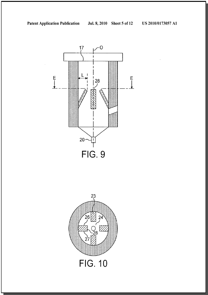
- 9. Device according to claim 1, wherein the diluent inlet is oriented in a direction so that the ratio of the orthogonal distance “d” to the radius “r” of the chamber is between 0.2 and 0.
- 9.
- 10. Device according to claim 1, wherein the diluent inlet is inclined downwardly in direction toward the bottom wall at an angle (b) relative to a transversal plane.
- 11. Device according to claim 10, wherein the angle (b) relative to transversal plane of the chamber is between 5 and 30 degrees.
- 12. Device according to claim 1, comprising two diluent inlets located at different heights of the chamber upward wall.
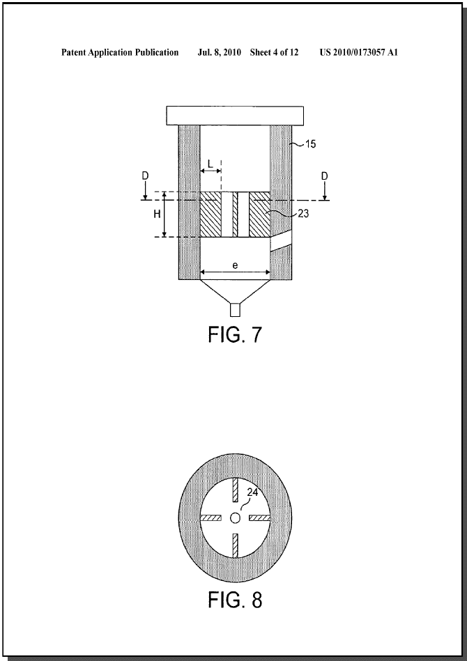
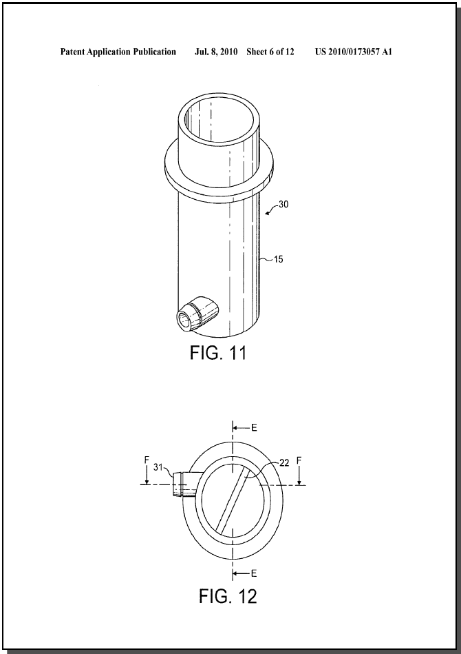
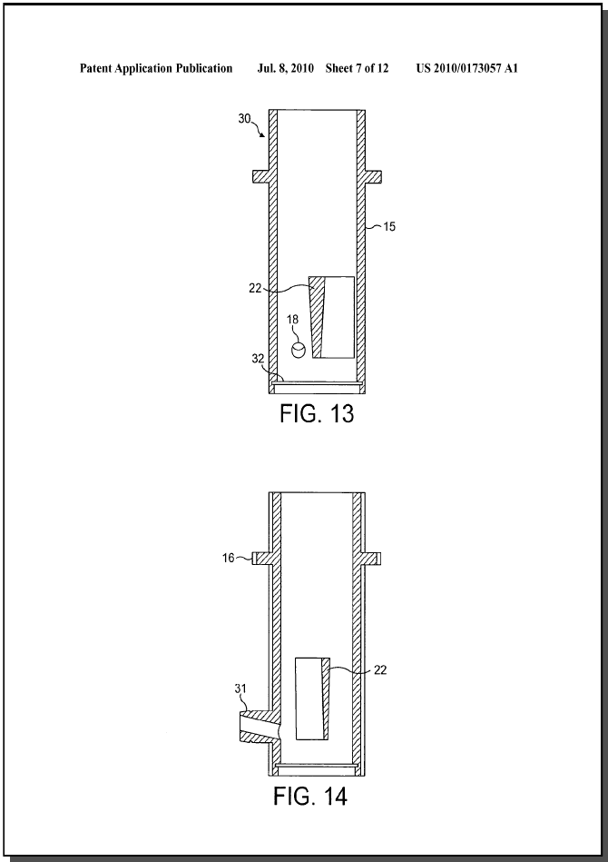
- 13. Device according to claim 1, comprising at least one baffle means placed at least partially across the chamber.
- 14. Device according to claim 13, wherein at least one baffle means is placed above the diluent inlet.
- 15. Device according to claim 14, comprising a plurality of baffles vertically oriented along and/or inclined relative to the longitudinal central axis.
- 16. Device according to claim 13, wherein at least one baffle means faces at least one diluent inlet.
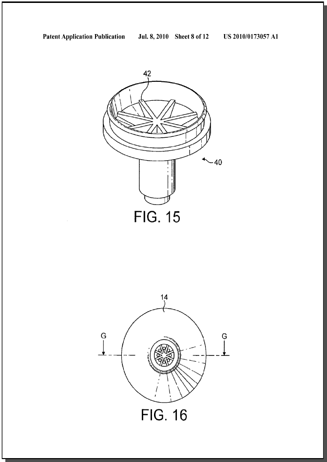
- 17. Device according to claim 16, wherein the baffle means are placed totally across the chamber and comprise orifices.
- 18. Device according to claim 17, wherein the baffle means are a sieve.
- 19. Device according to claim 18, wherein the sieve comprises a number of eyes per cm<2 >of between 50 and
- 100.
- 20. Device according to claim 16, comprising two diluent inlets, one diluent inlet being placed above the baffle means.
- 21. Device according to claim 1, wherein the chamber comprises a conduit placed at the top of the chamber the conduit providing a liquid outlet allowing liquid to exit the chamber after the liquid has exceeded the chamber capacity.
- 22. Device according to claim 1, wherein it forms a disposable or recyclable cartridge which contains an amount of soluble ingredient.
- 23. Device according to claim 22, wherein the diluent inlet and air aperture are hermetically closed by at least one airtight removable membrane.
- 24. Beverage production apparatus comprising a device for producing a frothed liquid comprising: an opened chamber having a transverse bottom wall and a longitudinal upward wall,at least one diluent inlet,at least one liquid delivery outlet,the diluent inlet is provided through the upward wall and directs a jet of diluent into the chamber,the liquid delivery outlet is configured in the bottom wall for enabling liquid to rise up along the side of the upward wall by the jet of diluent entering the chamber as a result of the direction and dimension of the diluent inlet in the chamber comprising diluent feed means which is connectable to the diluent inlet.
- 25. Method for producing a frothed liquid in a beverage production apparatus comprising: providing a chamber with a transverse bottom wall and a longitudinal upward wall,dosing the chamber with soluble ingredient,feeding a diluent through a diluent inlet to create a jet of diluent in the chamber and mix the diluent with said soluble ingredient to dissolve it into a liquid,controlling the liquid flow delivered out of the chamber in such a manner that the liquid can rise up to a certain level along the side of the upward wall when diluent is fed into the chamber and for the liquid to form a sheared surface of liquid which is impacted, as a result of the direction and dimension of the diluent inlet in the chamber, by the jet of diluent, andstopping the diluent intake inside the chamber and draining the frothed liquid from the chamber at at least one outlet.
- 26. Method according to claim 25, comprising controlling the liquid flow delivered out of the chamber by delaying the liquid flow out of the chamber relative to the intake of diluent inside the chamber.
- 27. Method according to claim 25, comprising feeding the diluent in the chamber by passing the diluent through a diluent inlet and orienting the diluent jet in a direction inside the chamber which is offset relative to the longitudinal central axis of the chamber.
- 28. Method according to claim 27, wherein the oriented diluent jet is through a sieve placed across the chamber.
- 29. Method according to claim 25, wherein a soluble coffee ingredient is dosed in the chamber.
- 30. Method according to claim 25, comprising further rinsing the chamber by passing diluent through the diluent inlet after draining of the frothed liquid in the chamber and further draining the rinsing liquid.
- 31. A device for producing a frothed liquid comprising: a chamber having a bottom wall and an upward wall,at least one diluent inlet,at least one liquid delivery outlet,the diluent inlet is so constructed and arranged dimensioned and oriented for directing a jet of diluent into the chamber,the liquid delivery outlet is located in the bottom wall is so constructed and arranged that liquid rises up along the side of the upward wall as a result of the jet of diluent from the diluent inlet in the chamber.