


US2019223656 (A1)
Beverage preparation machine with a controlled pump.
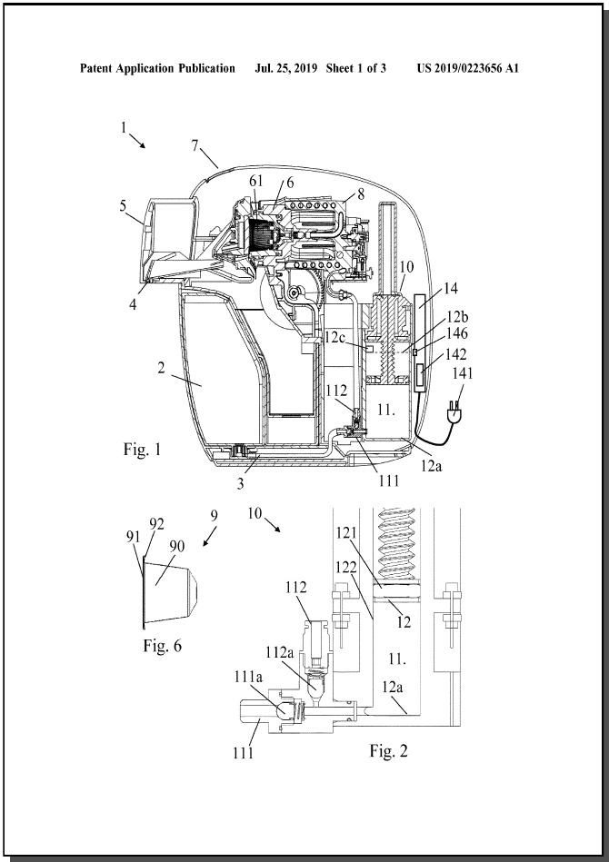
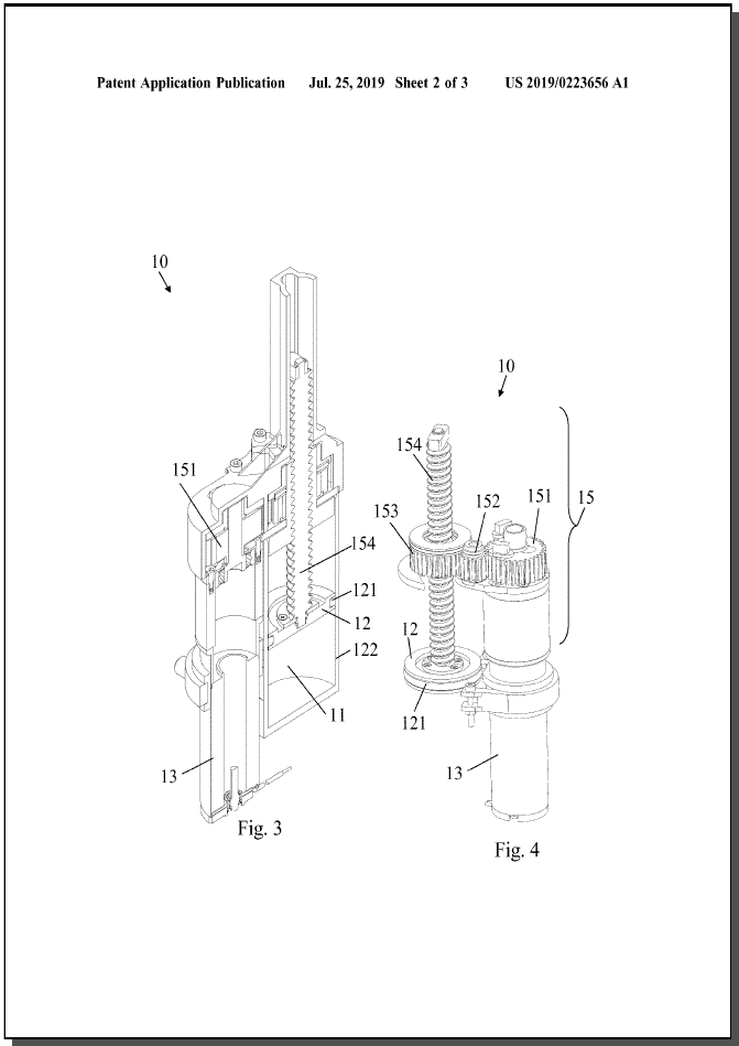
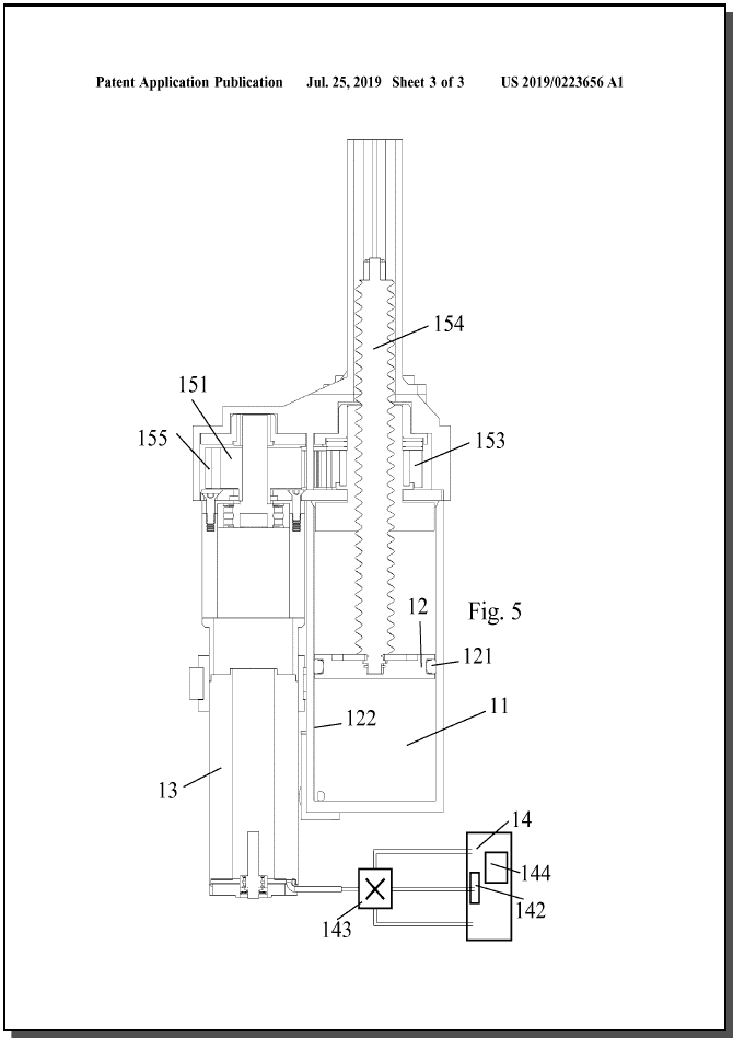
[0001] A beverage preparation machine (1) comprises a source of liquid (2,3) and a dispensing outlet (4) connected via a pump (10) that includes a chamber (11) and a displaceable wall (12) delimiting the chamber (11). The pump (10) further has: an electric actuator (13) driving the displaceable wall (12) for causing an inflow of liquid from the source into the chamber (11) and for causing an outflow of liquid from the chamber (11) to the dispensing outlet (4); and a powering unit (14) that comprises an electric power source (142) and that is configured for supplying power to the actuator (13). The powering unit (14) further comprises: a sensor (143) for measuring an electrical parameter representative of a consumption of power by the actuator (13); and a control unit (144) that is connected to the sensor (143) and to the electrical power source (142) and that is configured to control the power supplied to the actuator (13) by the electric power source (142) as a function of: the measured parameter; and a desired liquid input into the chamber (11) and/or liquid output from the chamber (11), such as a desired flow and/or pressure of the liquid input and/or of the liquid output.
- Publication
- US2019223656 (A1)
- Publication date
- 2019-07-25
- Priority date
- 2016-06-30
- Inventors
- THULIEZ JEAN-LUC [CH]; OBLIGER NICOLAS [FR]; CROZIER ETIENNE [CH]; GUYON BERTRAND [FR]; MAGATTI MARCO [CH]
- Applicants
- NESTEC SA [CH]; NESTLE SA [CH]
- Classification
- Classification: - internationale A47J31/34; A47J31/46; A47J31/52 - coopérative A47J31/34 (RU, US); A47J31/3623 (US); A47J31/3633 (EP, RU); A47J31/46 (EP, RU); A47J31/468 (RU, US); A47J31/525 (EP, RU, US); A47J31/5251 (EP, RU, US); A47J31/5253 (EP, RU, US); A47J31/5255 (EP, RU, US);
Patent family publications
Project images
Description
FIELD OF THE INVENTION
[0001] The present invention concerns beverage preparation machines with a controlled pump.
[0002] For the purpose of the present description, a “beverage” is meant to include any liquid food, such as tea, coffee, hot or cold chocolate, milk, soup, baby food, etc... A “capsule” is meant to include any pre-portioned beverage ingredient within an enclosing packaging of any material, in particular an airtight packaging, e.g.
[0003] plastic, aluminium, recyclable and/or biodegradable packagings, and of any shape and structure, including soft pods or rigid cartridges containing the ingredient. BACKGROUND ART
[0004] Beverage preparation machines have been known for a number of years. For example, U.S. Pat. No. 5,943,472 discloses a water circulation system between a water reservoir and a hot water or vapour distribution chamber of an espresso machine. Suitable pumps for beverage machines are for instance disclosed in U.S. Pat. No. 2,715,868, 5,392,694, 5,992,298, 6,554,588, WO 2004/014205, WO 2005/053489, WO 2006/005425, WO 2006/032599, WO 2009/150030 and WO 2010/108700. EP 2 247 857, EP 2 643 588 and EP 2 904 266 disclose a pump with a pump chamber that is associated with a heater for heating liquid in the pump chamber. WO 2004/014205 and WO 2005/053489 teach the use of a pressurized gas source for pressurizing and driving liquid in a beverage machine. WO 2006/005425 discloses the use of a peristaltic pump for driving a liquid in a beverage machine. U.S. Pat. No. 2,715,868 discloses a beverage preparation machine with a pump of the rotary type. U.S. Pat. No. 5,392,694 discloses an espresso machine with a pump that has a piston actuated by an eccentric drive via a connecting rod engaged. SUMMARY OF THE INVENTION
[0005] A preferred object of the present invention concerns a beverage machine with a simple pump configuration adapted to provide a reliable pump performance control.
[0006] Therefore, the invention relates to a beverage preparation machine comprising a source of liquid and a dispensing outlet connected via a pump.
[0007] The pump has a chamber and a displaceable wall delimiting the chamber. The displaceable wall being for instance joined to the adjacent (typically static) chamber wall(s) by a seal, e.g. an O-ring. The pump further has an electric actuator driving the displaceable wall between a first position and a second position for causing an inflow of liquid from the source into the chamber and for causing an outflow of liquid from the chamber to the dispensing outlet optionally via a thermal conditioner such as a heater and/or cooler.
[0008] The pump also has a powering unit that comprises an electric power source and that is configured for supplying power to the actuator. The powering unit can have an electric plug or connector for connection to the mains or a different power supply, e.g. a battery or transformer (DC) and/or renewable energy supply (solar photovoltaic supply).
[0009] The powering unit includes a sensor for measuring at least one electrical parameter representative of a consumption of power by the actuator from the source. The powering unit further includes a control unit connected to the sensor and to the electrical power source. The control unit is configured to control the power supplied to the actuator by the electric power source as a function of: the at least one measured parameter; and a desired liquid input into the chamber and/or a desired liquid output from the chamber, such as a desired flow and/or pressure of the liquid input and/or of the liquid output.
[0010] Hence, a sensor of the electric consumption by the pump's actuator can be used to determine the performance of the pump and to adjust the powering of the pump accordingly.
[0011] The sensor can be at least one of an ammeter (e.g. a hall sensor), voltmeter and potentiometer.
[0012] The incorporation of a sensor for measuring at least one electrical parameter representative of a consumption of power by the pump's actuator can replace the use of a flowmeter or a pressure sensor for measuring the performance of the pump.
[0013] The control unit may control: a thermal conditioner, such as a heater and/or cooler; and/or the opening and closing of an ingredient unit and/or a gate leading thereto.
[0014] The control unit can be connected by wired or wireless connection to a machine's user-interface (i.e. a user-interface incorporated in the machine) or to a communication module for communicating with an external device (i.e. a remote device), e.g. a network and/or a portable device (e.g. smartphone).
[0015] The pump can have one, two or more cavities.
Claims
- 1. A beverage preparation machine comprising a source of liquid and a dispensing outlet connected via a pump comprising: a chamber;a displaceable wall defining the chamber;an electric actuator driving the displaceable wall between a first position and a second position for causing an inflow of liquid from the source into the chamber and for causing an outflow of liquid from the chamber to the dispensing outlet; anda powering unit that comprises an electric power source and that is configured for supplying power to the actuator,the powering unit further comprises:a sensor; anda control unit connected to the sensor and to the electrical power source, the control unit being configured to control the power supplied to the actuator by the electric power source as a function of:the at least one measured parameter; anda desired liquid input into the chamber and/or a desired liquid output from the chamber.
- 2. The machine of claim 1, wherein the chamber has a pump inlet in fluidic connection with the source of liquid and a pump outlet in fluidic connection with the dispensing outlet, the pump inlet having an anti-return valve for preventing an outflow of liquid from the chamber via the inlet, the pump outlet having an anti-return valve for preventing an inflow of liquid into the chamber via the outlet.
- 3. The machine of claim 1, wherein the chamber comprises an upstream cavity with a pump inlet and a downstream cavity with a pump outlet, the first and second cavity being connected via an anti-return valve in the displaceable wall located between downstream cavity and the upstream cavity, the anti-return valve permitting a flow of liquid from the upstream cavity to the downstream cavity and preventing an opposition flow.
- 4. The machine of claim 1, wherein the actuator comprises a motor connected to the displaceable wall by a transmission.
- 5. The machine of claim 4, wherein the transmission comprises a gear arrangement.
- 6. The machine of claim 4, wherein the transmission comprises at least one chain or belt.
- 7. The machine of claim 1, wherein the control unit is configured to control the electric power source to supply a desired voltage to the electric actuator.
- 8. The machine of claim 1, wherein the control unit is configured to control the electric power source to supply a desired current to the electric actuator.
- 9. The machine of claim 1, wherein the control unit is configured to: carry out a comparison; andcontrol the power supplied to the actuator as a function of the comparison.
- 10. The machine of claim 9, wherein the control unit is configured to adjust: a voltage intake by the actuator from the power supply to ensure a desired current intake by the actuator derived from measuring with the sensor; and/ora current intake by the actuator from the power supply to ensure a desired voltage intake by the actuator derived from measuring with the sensor the voltage intake as at least one parameter.
- 11. The machine of claim 9, wherein the control unit is configured to take a safety measure when: the difference between the measured parameter and the predetermined reference exceeds a tolerance value; and/orthe measured parameter increases or decreases at a rate that is greater in absolute value than a predetermined threshold value.
- 12. The machine of claim 1, wherein the control unit is configured to interrupt the powering of the actuator hen the displaceable wall defining the chamber reaches an end wall of the chamber or a physically-determined or sensor-determined end position.
- 13. The machine of claim 1, wherein the pump is configured to drive the liquid from the source towards the outlet via a unit arranged to receive a beverage ingredient.
- 14. The machine of claim 13, wherein the control unit is configured to: carry out a comparison of the at least one measured parameter and a predetermined reference associated with the ingredient; andcontrol the power supplied to the actuator as a function of the comparison.
- 15. (canceled)