


US2011061534 (A1)
BEVERAGE PRODUCTION DEVICE.
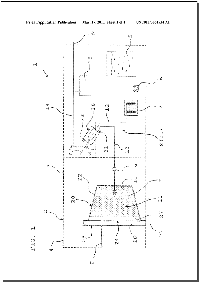
The invention as claimed shows a beverage production device (1) comprising a beverage production chamber (20) designed to have a liquid interact with a beverage ingredient (T) contained in a capsule, liquid supply means (8) for supplying liquid to said beverage production chamber (20), heating means (7) provided in the liquid supply means (8) for heating the liquid, and an air separating compartment (30) provided in the liquid supply means (8) after the heating means (7) for separating any air or other gas contained in the liquid, wherein the air separating compartment (30) comprises an inlet (35) for introducing liquid into the air separating compartment (30), means for breaking the kinetic energy of the liquid introduced through the inlet (35), a liquid outlet (37), separated from the inlet by the means for breaking the kinetic energy of the liquid introduced through the inlet (35), for evacuating liquid from the air separating compartment (30), and an air outlet (39), also separated from the inlet by the means for breaking the kinetic energy of the liquid introduced through the inlet (35), for evacuating air from the air separating compartment (30). Hence, a beverage production device (1) is provided having a reduced amount of air in the liquid used for extraction of the beverage ingredient (T).
- Publication
- US2011061534 (A1)
- Publication date
- 2011-03-17
- Priority date
- 2008-05-08
- Inventors
- THULIEZ JEAN-LUC [CH]; OZANNE MATTHIEU [FR]; VUAGNIAUX DIDIER [CH]; ROBERT THIERRY [CH]
- Applicants
- THULIEZ JEAN-LUC [CH]; OZANNE MATTHIEU [FR]; NESTEC SA [CH]; VUAGNIAUX DIDIER [CH]; ROBERT THIERRY [CH]
- Classification
- Classification: - internationale A47J31/40; A47J31/44; B01D19/00 - coopérative A47J31/36 (KR); A47J31/461 (EP, KR, US); B01D19/0042 (EP, KR, US)
Patent family publications
Project images
Description
[0001] The present invention relates to a beverage production device for preparing a beverage from a beverage ingredient provided to the device. More particularly, the invention relates to such a device comprising a beverage production chamber in which a liquid is made to interact with said beverage ingredient, the beverage ingredient particularly being contained in pre-portioned form in a closed capsule.
[0002] Devices for preparing a beverage by injecting, for instance, pressurized fluid to a capsule are well-known, especially in the field of producing tea, coffee or coffee type beverages. In addition, other substances such as chocolate or milk products can be extracted or dissolved to form a beverage. The advantages of such a system are in particular the conservation and freshness of the ingredients, as well as the possibility of facilitating the operations when preparing the beverage.
[0003] It should be understood that the interaction between the liquid and the ingredients within, for example, the capsule can be e.g. dissolving, extraction, brewing or any other interaction in order to prepare a beverage by means of ingredients provided within the capsule. Such a capsule is yet known from the patent documents WO 2007/042414 A1 and WO 2008/025730 A1 and mainly comprises an enclosure defined by a housing or shell and a filtering means.
[0004] When, for instance, preparing tea in such a device a problem occurs due to the presence of air in the liquid (e.g. water) being delivered to the capsule. This air mainly comes from the heating of the water which is carried out by a heater provided in the supply means for supplying the liquid to the beverage production chamber of the device. The air or air bubbles appear as soon as the liquid (water) temperature reaches about 70° C. The air is thus introduced with the liquid into the capsule but tends to not traverse the filter means (generally a paper filter) that is placed inside the capsule as described above. As in a low pressure water flow, which is present when preparing e.g. tea, there is no important stirring of water and of the product to be brewed (beverage ingredient like powder), the air bubbles can separate from the liquid, slowly raise to the top of the beverage production chamber like a capsule, for instance, and stay behind the filter inside the capsule. Their volume grows as long as water is injected inside the capsule. However, this volume can become so important that, for instance, the tea leaves are no longer properly immersed inside the liquid (water) and the tea can thus be not sufficiently extracted.
[0005] The present invention has been achieved in view of the above-mentioned drawbacks, and an object thereof is to provide a beverage production device having a reduced amount of air in the liquid used for extraction of the beverage ingredient.
[0006] According to a first aspect of the invention there is provided a beverage production device which comprises a beverage production chamber designed to have a liquid interact with a beverage ingredient contained in a capsule, liquid supply means for supplying liquid to said beverage production chamber, heating means provided in the liquid supply means for heating the liquid, and an air separating compartment provided in the liquid supply means after the heating means for separating any air or other gas contained in the liquid. The air separating compartment comprises an inlet for introducing liquid into the air separating compartment, means for breaking the kinetic energy of the liquid introduced through the inlet, a liquid outlet, separated from the inlet by the means for breaking the kinetic energy, for evacuating liquid from the air separating compartment, and an air outlet, also separated from the inlet by the means for breaking the kinetic energy, for evacuating air from the air separating compartment.
[0007] By means of the above described feature, an effectively decrease in liquid flow velocity arises when the liquid entering the air separating compartment. Hence, it is possible to reduce the liquid flow velocity such that air or gas is not carried along inside the liquid by the speed of the liquid, and the air can thus rise in order to be evacuated by the air outlet, and the separation of air from the heated liquid is realised.
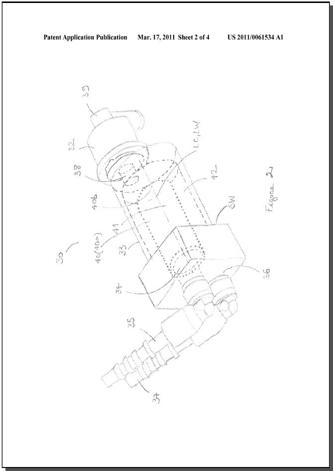
[0008] According to a first embodiment of the present invention, the means for breaking the kinetic energy of the liquid introduced through the inlet is a porous wall. The porous wall can form a porous chamber inside the air separating compartment. In a preferred way the porous chamber presents a cylinder shape. The porous wall can be a sieve or a filter. By means of the above described features, it is possible to easily reduce the amount of air in heated liquid as the air is trapped in the meshes of the porous wall and can thus easily rise to an upper portion of the air separating compartment where it can be evacuated through the air outlet while the airless liquid can be evacuated through the liquid outlet.
[0009] A simple element having a common material can be used for separating air or other gas from a heated liquid as the gas is trapped in the meshes of said sieve or filter element. Preferably, the porous wall forms a porous chamber inside the air separating compartment. In order to have the liquid outlet and the air outlet separated from the inlet by the porous wall, the porous wall is preferably placed inside the air separating compartment so that it encircles the liquid inlet inside the air separating compartment thus forming the porous chamber. The porous chamber 41an present any shape. It is preferably a cylinder, the basis of which is the part of the air separating compartment sidewall surrounding the liquid inlet. Preferably, the longitudinal axis of the air separating compartment and the longitudinal axis of the porous chamber are substantially aligned. The liquid inlet can be provided at a substantially central position of the sidewall of the air separating compartment corresponding with the longitudinal axis of the air separating compartment and the porous chamber. By means of the above described feature a uniform inflow of the liquid into the air separating compartment and an equal distribution of the liquid inside the air separating compartment can be attained.
[0010] The porous chamber 41an be inclined with respect to horizontal axis, and its longitudinal axis raising according to the flow direction. By means of said feature, the separation of air and liquid can be easily achieved as the air can easily rise up to the highest portion of the air separating compartment while the liquid can simply be evacuated from a lower portion of the air separating compartment.
[0011] The air separating compartment preferably presents a volume sufficient to dampen the flow of the liquid entering in it. For this reason, it is preferred that the section area of the inlet and the section area of the air separating compartment are at a ratio of at least 1:10, preferably at least 1:100. Said sections are essentially perpendicular to the liquid flow direction either in the inlet or in the air separating compartment.
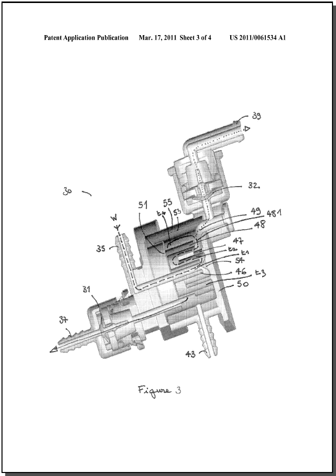
[0012] According to a second preferred embodiment, the means for breaking the kinetic energy of the liquid introduced through the inlet can be means for changing the direction of the liquid. Preferably, the means for breaking the kinetic energy of the liquid introduced through the inlet changes the direction of the liquid flow path to the opposite direction of the liquid at least twice. This change of direction of the liquid flow path to the opposite direction means that the direction of the liquid flow is essentially changed about an angle of 180°. More preferably, at least two changes to the opposite direction of the liquid flow path are provided by the specific design of the means for breaking the kinetic energy of the liquid. Accordingly, the fluid velocity can be effectively decreased. Such means can preferably be selected between baffles or a labyrinth flow path. Preferably, the fluid section through the means for breaking the kinetic energy of the liquid is increased each time there is a change of direction of the fluid flow path through said means.
[0013] According to the preferred embodiment, the means for breaking the kinetic energy of the liquid is a labyrinth formed by at least three concentrically arranged cylindrical members which are designed to force liquid provided by the inlet to meander from a centre portion of the labyrinth to a rim portion thereof. The cylindrical members can be arranged to form at least two interstitial spaces between the cylindrical members. Preferably, the interstitial spaces between the cylindrical members are gradually increased from the centre to the rim portion of the labyrinth. Preferably the larger cylindrical member is connected to the rim portion of the labyrinth by an orifice placed at the upper part of the larger cylindrical member. The upper part of the labyrinth rim portion is preferably connected to the air outlet and the bottom part of the labyrinth rim portion is connected to the liquid outlet.
[0014] According to a preferred aspect of the invention, the liquid outlet is provided with a first valve. By means of said valve, the value of the pressure at which the valve is opened can be set to a liquid pressure needed for the liquid to be supplied to the beverage production chamber and for beverage production. Hence, an additional backpressure valve in the liquid supply means before the beverage production chamber 41an be omitted.
[0015] According to another preferred aspect of the invention, the air outlet is provided with a second valve. By means of said valve, sufficient deaeration can be attained without any liquid escaping through said valve.
[0016] Preferably the value of pressure for opening the first valve is greater than that of the second valve. Then deaeration can already be accomplished before liquid is evacuated from the air separating compartment. Hence, the chance of separated air to be mixed again with airless liquid is reduced and thus, the liquid being supplied to the beverage production chamber merely contains a minimum of air or other gas. The value of pressure for opening the first valve can be at least 0.2 bar, preferably at least 0.4 bar. Thus, the liquid is supplied to the beverage production chamber at an appropriate pressure for beverage production.